


– 101 –
APPENDIX
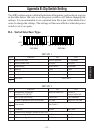
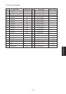
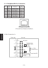
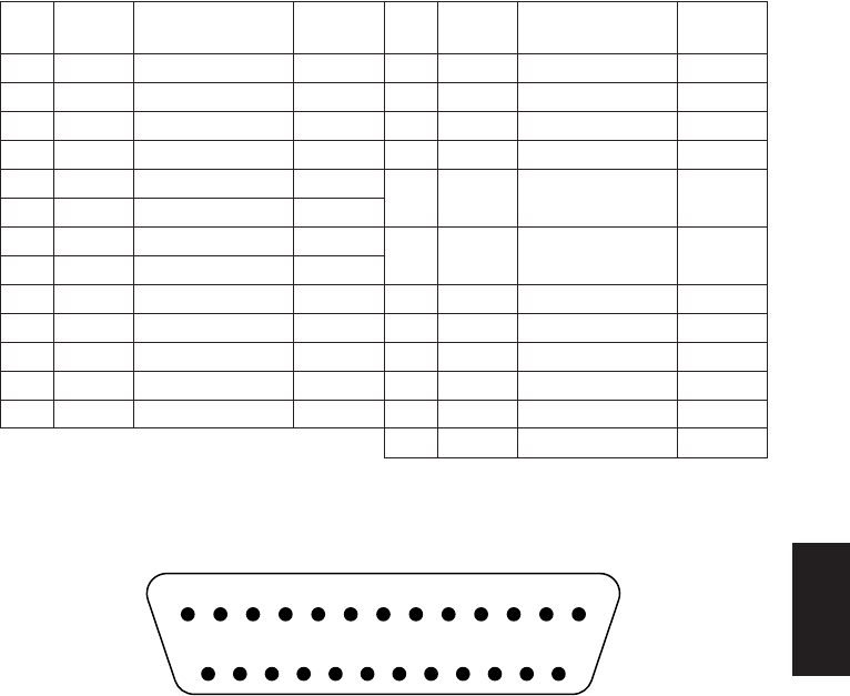
C-1-2. RS-232C Connector
Pin No.
Signal
Function
I/O
name direction
Pin No.
Signal
Function
I/O
name direction
1 FG Frame ground
2 TXD Send data OUT
3 RXD Receive data IN
4 RTS Request to send OUT
5 CTS Clear to send IN
6 DSR Data set ready IN
7SG
8–
9–
10 –
11 –
12 –
*13 SG2 Ground for +24V IN
*14 SG2 Ground for +24V IN
15 –
16 –
17 –
*18 +24V
Drive power for
IN
mechanical section
*19 +24V
Drive power for
IN
mechanical section
20 DTR Data terminal ready OUT
21 –
22 –
23 –
24 –
25 INIT IN
The signals marked with “*” should not be used to supply power if the AC adapter
is used. Doing so may result in damage to the power supply.
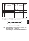
<Viewed from Connector Surface>
Note: Connector on printer side: DALC-J25PAF-23L8 (from Japan Avia-
tion Electronics Industry, Ltd.) or equivalent
Connector on cable: DA-25SF-N (from Japan Aviation Electronics
Industry, Ltd.) or equivalent
13 12 11 10 9 8 7 6 5 4 3 21
25 24 23 22 21 20 19 18 17 16 15 14