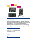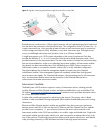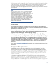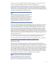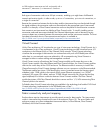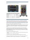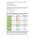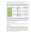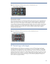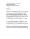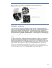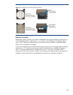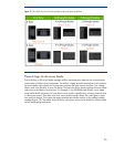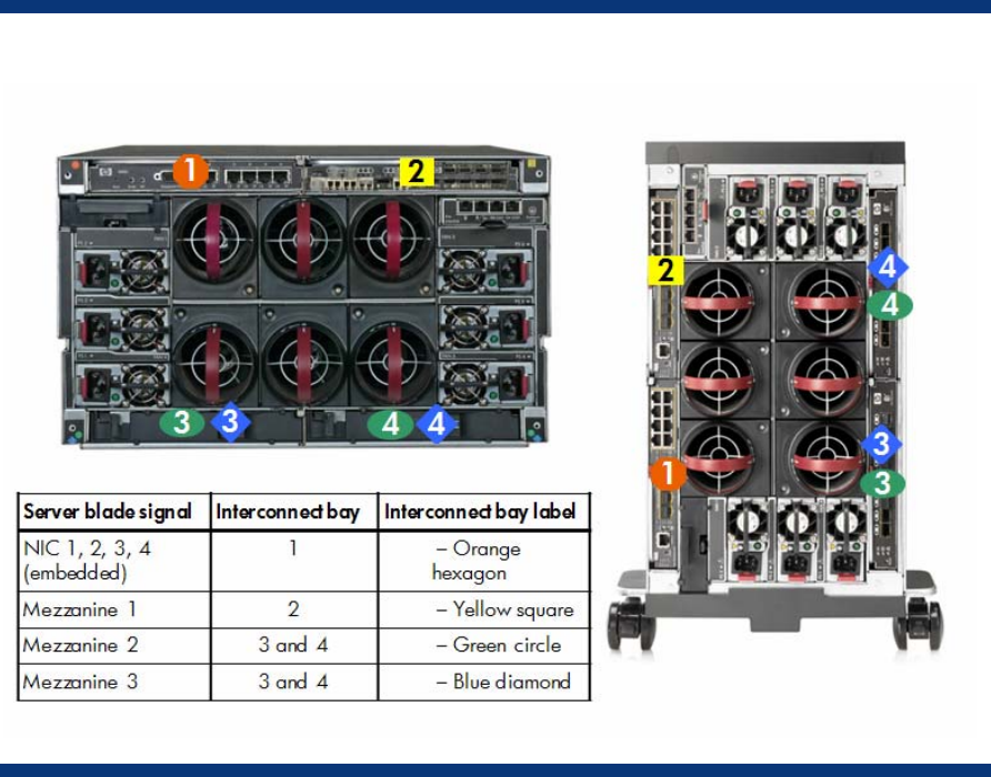
Figure 10. HP BladeSystem c3000 interconnect bay numbering
For interconnect bay mapping purposes, it does not matter in which device bay a server blade is
installed. The mezzanine connectors always connect to the same interconnect bays. Because the
connections between the device bays and the interconnect bays are hard-wired through the NonStop
signal midplane, the server mezzanine cards must be matched to the appropriate type of interconnect
module. For example, a Fibre Channel mezzanine card must be placed in the mezzanine connector
that connects to an interconnect bay holding a Fibre Channel switch.
Embedded NICs and adapters installed in Mezzanine 1 are supported by single-wide interconnects in
interconnect bays 1 and 2 respectively. Mezzanine 2 and 3 can be supported by either single-wide
or double-wide interconnects such as InfiniBand or 10 Gb Ethernet devices in interconnect bays 3
and 4.
An internal connection on the midplane between interconnect bays 1 and 2 and an additional
connection between interconnect bays 3 and 4 provide an internal link for use as a crosslink port
between interconnect bays 1 and 2 or interconnect bays 3 and 4. NIC teaming can be configured
between embedded NICs and Mezzanine 1 NICs using the internal crosslinks between the switches
through this internal connection.
Several port types are referenced in Figures 11 and 12:
• Examples of 1x ports are 1-Gb Ethernet (1-GbE) pass-thru modules and Fibre Channel interconnect
modules.
• An example of a 2x port is a SAS interconnect module.
• Examples of 4x ports are 10-GbE pass-thru modules and InfiniBand interconnect modules.
A full-height server blade plugs into two device bay connectors and has 32 lanes available to the 4
interconnect bays (16 lanes x 2 in Figure 12). Interconnect bay 1 is reserved for Ethernet
19


