ASUS TUEP2-M User’s Manual 37
3. HARDWARE SETUP
Connectors
3. H/W SETUP
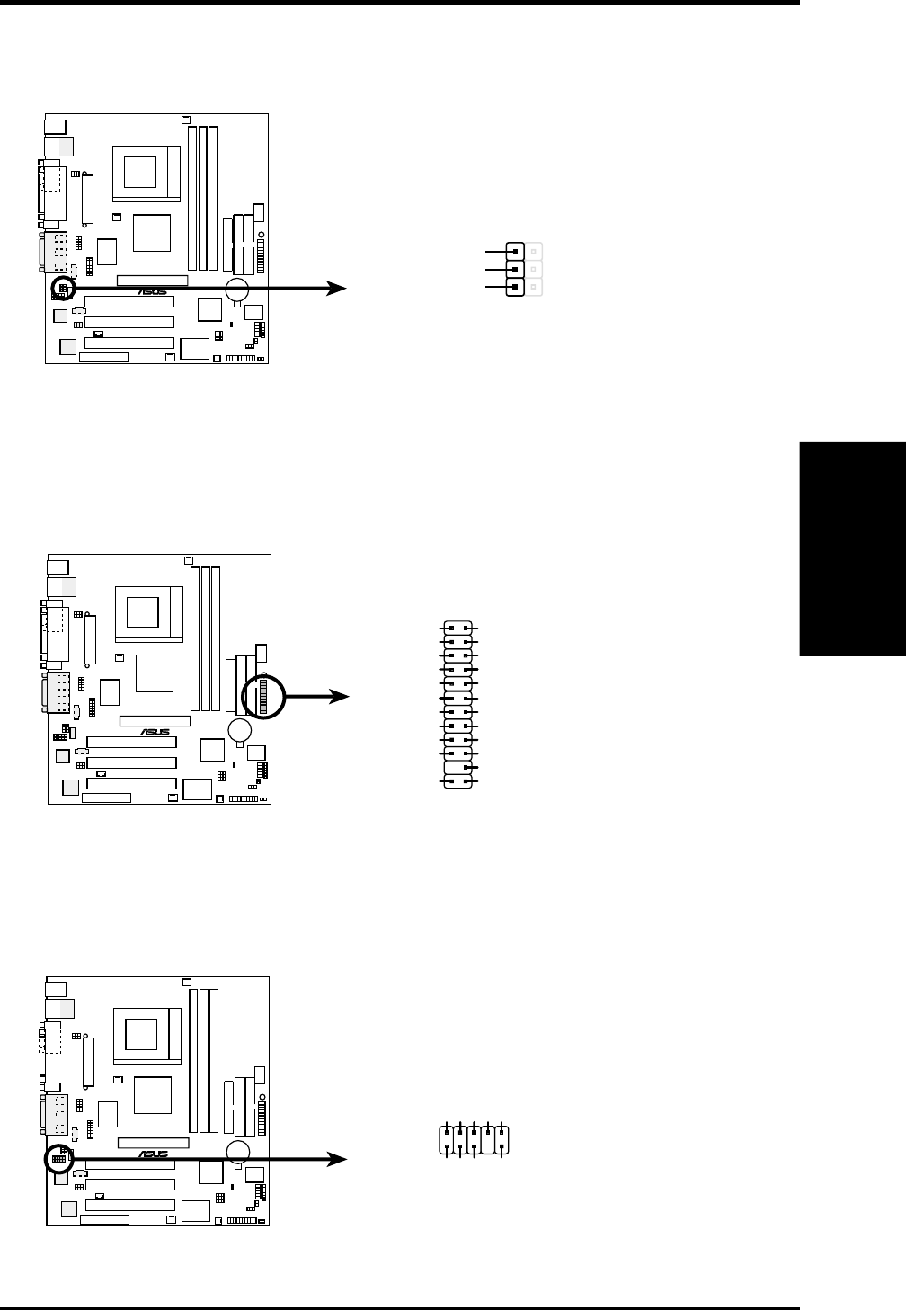
7) Internal Microphone Connector (3-pin MIC2)
This connector allows you to connect chassis mounted microphone to the
motherboard.
8) ASUS iPanel Connector (24-1 pin AFPANEL)
This connector allows you to connect an optional ASUS iPanel, an easy to access
drive bay with front I/O ports, status LEDs, and space reserved for a hard disk
drive.
9) ASUS iPanel Audio Connector (10-1 pin AAPANEL)
Connect the audio cable from the optional ASUS iPanel to this for front panel
audio control.
TUEP2-M
®
TUEP2-M Internal Microphone Connector
MIC2
MIC Power
1
3
MIC Input
Ground
TUEP2-M
®
TUEP2-M Front Panel Connectors
AFPANEL
+5VSB
NC
CHASSIS#
+5 V
PCIRST#
GND
CIRRX
EXTSMI#
MLED-
NC
BATT
NC
SMBDATA
GND
+3VSB
NC
IRRX
IRTX
LOCKKEY
NC
NC
+5VSMBCLK
TUEP2-M
®
TUEP2-M Audio Panel Connectors
MICPWR
Line in_R
Line in_L
MIC2
Line out_L
AGND
AGND2AGND3
Line out_R
AAPANEL


