


96047 First Edition 2-3
Controls and Indicators
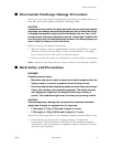
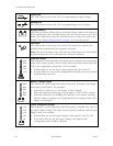
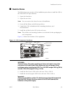
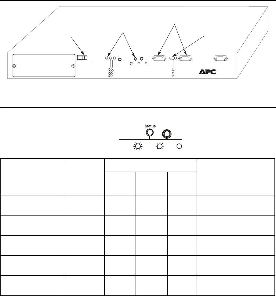
■ Redundant Switch Indicators
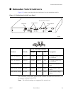
Figure 2-2 shows and describes the indicators for the redundant switch:
The redundant switch front panel has the controls and indicators that allow you
to program settings for the UPS.
Note: The default settings are suggested for normal use.
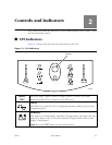
Figure 2-2. Redundant Switch Front Panel
EPO
Emergency
Power Off
Function
Source A Sensitivity
Source B Sensitivity
Source Preference
Source A Xfer Voltage
Source B Xfer Voltage
Bright Dim Off
Normal
Source A
Normal
Narrow
Narrow
Reduced
Source B
Medium
Reduced
Medium
Low
None
Wide
Low
Wide
Source selected
Source OK, but not selected
Source not OK
Level
Redundant Switch
C6
7
350
EPO Switch
Status Indicators
UPS Serial Port Connections
Source Indicators
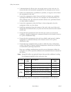
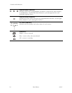
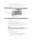
User Selectable Options
Function Default Bright Dim Off Description
Source A Sensitivity Reduced Normal Reduced Low Sets transfer sensitivity to
line conditions
Source B Sensitivity Reduced Normal Reduced Low Sets transfer sensitivity to
line conditions
Source Preference Source A Source A Source B None Selects the preferred AC
source
Source A Xfer Voltage Medium Narrow Medium Wide Sets the transfer voltage
window
Source B Xfer Voltage Medium Narrow Medium Wide Sets the transfer voltage
window
Bright Dim
Off
Level
Select