


Chapter 2 Hardware Installation 39
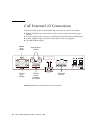
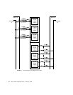
System Console Terminal Connections
The system console and modem connections are provided on separate 25-pole
female D-type connectors.
TABLE 2-4 shows the pin allocation on these connectors.
Except for pin 1, all pins of the console and modem connectors are isolated from the
frame ground of the Netra ft 1800 system.
The connectors have two screw-threaded mounting pillars with 4-40 UNC threads.
You should secure the cable headshell in place with the screws engaged in these
pillars. If you use a cable headshell without securing the screws, make sure that the
pillars do not prevent full engagement of the connector. This can happen with some
types of cable headshell where screw heads can foul against the mounting pillars.
You must also secure the other end of the cable to the console terminal if the
terminal provides some means of locking.
Note – To ensure EMC compliance always use a high quality screened cable that has
metal connector shells.
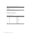
TABLE 2-5 shows the console terminal configuration parameters for both console and
modem ports. You can modify these parameters using Solaris utilities.
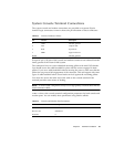
TABLE 2-4 Console Connector Pinout
Pin Function Description
1 GND Chassis ground
2 TxD Output data
3 RxD Input data
7 SREF Signal reference
Shield Chassis ground
TABLE 2-5 Console and Modem Port Parameters
Parameter Setting
Transmit rate 9600 baud
Receive rate 9600 baud
Data bits 8