Power Supply Installation 2-25
2
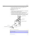
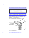
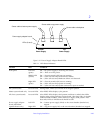
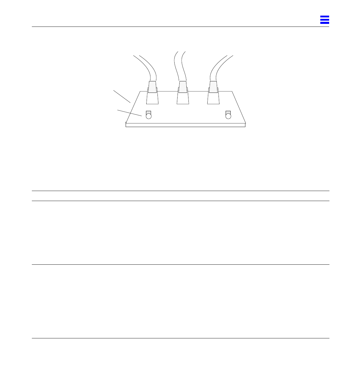
Figure 2-23 Power Supply Adapter Board LEDs
Table 2-1 LED Status Indicators
Location LED Condition
Front panel Left LED
(green)
On — DC power supply is receiving AC current.
Off — There is no DC power.
Middle LED
(yellow)
On — (first 60 seconds) Self tests are running.
Off — (after self tests end) No hardware failures.
On — (after self tests end) Hardware failure was detected.
Right LED
(green)
Off — (first 60 seconds) Self tests are running.
On — (after self tests end) System is running.
Off — (after self tests end) System cannot run; repair is needed.
All system boards Lower 8 LEDs During POST, LEDs cycle on and off in irregular pattern.
Master system board only Lower 8 LEDs After POST, LEDs display cyclic pattern.
All slave system boards Lower 8 LEDs After POST, LEDs display solid pattern until boot is ended, then LEDs
display same cycling pattern as master board. After boot ends, for boards
without SPARC modules, LEDs continue to display solid pattern. After
boot ends, LEDs on failed boards should be OFF.
Power supply adapter
board (redundant-
capable chassis only)
Left LED
Right LED
On — bottom power supply failed, or the circuit breaker (breaker box)
tripped.
Off — top power supply fail, or the circuit breaker (breaker box) tripped.
Power supply adapter board
Sense cable to bottom power supply
Sense cable to backplane
Sense cable to top power supply
Bottom
Power Supply
Top
Power Supply
LEDs (2 each)


