


Chapter 3 Sun StorEdge A3500/A3500FC Configurations 3-11
3.2 1x2 Cables and Connections
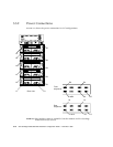
This section contains information about SCSI and power connections for one
StorEdge A3500 with two StorEdge D1000 disk arrays.
Note – The 1x2 configuration is not qualified on the A3500FC controller module.
In the 1x2 configuration, the controller module can be either on top of or below the
two disk arrays. Both configurations are described in this section.
Tip – Do not place the controller module at the bottom of the rack because the
controller board diagnostic LEDs will not be visible.
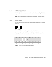
3.2.1 Driveside SCSI Connections
The following table shows the length of each SCSI cable connected to the drive
connections on the controller module.
The inboard IN/OUT connectors on each disk array are terminated with a
differential SCSI terminator, part number 150-1890.
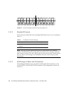
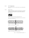
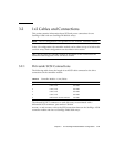
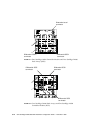
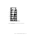
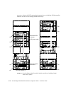
FIGURE 3-11 and FIGURE 3-12 show the SCSI connections between the StorEdge A3500
controller module and the two StorEdge D1000 disk arrays.
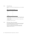
TABLE 3-6 Controller Module A (1x2) Cables
SCSI Port Number Cable Length Part Number
1 0.8m/2.6 ft 530-1884
2 0.8m/2.6 ft 530-1884
3 0.8m/2.6 ft 530-1884
4 0.8m/2.6 ft 530-1884
5 Differential SCSI terminator 150-1890