


31
E
n
t
erpr
i
se-
Cl
ass
S
o
ft
ware Sun Microsystems, Inc.
By taking advantage of Logical Domains, organizations gain the flexibility to deploy
multiple operating systems simultaneously on a single platform. In addition,
administrators can leverage virtual device capabilities to transport an entire software
stack hosted on a Logical Domain from one physical machine to another. Logical
Domains can also host Solaris Containers to capture the isolation, flexibility, and
manageability features of both technologies. Deeply integrating Logical Domains with
both the UltraSPARC T2 processor and the Solaris 10 OS increases flexibility, isolates
workload processing, and improves the potential for maximum server utilization.
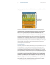
The Logical Domains architecture includes underlying server hardware, hypervisor
firmware, virtualized devices, and guest, control, and service domains. The hypervisor
firmware provides an interface between each hosted operating system and the server
hardware. An operating system instance controlled and supported by the hypervisor is
called a guest domain. Communication to the hypervisor, hardware platform, and other
domains for creation and control of guest domains is handled by the control domain.
Guest domains are granted virtual device access via a service domain which controls
both the system and hypervisor, and also assigns I/O.
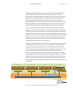
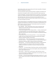
To support virtualized networking, Logical Domains implement a virtual Layer 2 switch,
to which guest domains can be connected. East guest domain can be connected to
multiple
vswitches
and multiple guest domains can also be connected to the same
vswitch. Vswitches can either be associated with a real physical network port, or they
may exist without an associated port, in which case the vswitch provides only
communications between domains within the same server. This approach also gives
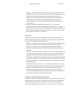
guest domains a direct communication channel to the network (Figure 13). Each guest
domain believes it owns the entire NIC and the bandwidth it provides, yet in practice
only a portion of the total bandwidth is allotted to the domain. As a result, every NIC
can be configured as demand dictates, with each domain receiving bandwidth on an as-
needed basis.
Figure 13. Data moves directly between a Logical Domain and a virtualized device
Hypervisor
I/O Bridge
Logical Domain 1
Virtual Ethernet Driver
User
Application
User
Application
User
Application
Logical Domain 2
Virtual Ethernet Driver
User
Application
User
Application
User
Application
Logical Domain 3
Virtual Ethernet Driver
User
Application
User
Application
User
Application
Service Domain
Virtual
Ethernet
Bridge
Virtual
Ethernet
Bridge
Device
Driver
Virtual Network 1
Virtual Network 2
Shared
Network
Interface