


Chapter 1 Initial Inspection of the Server 5
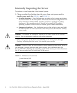
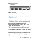
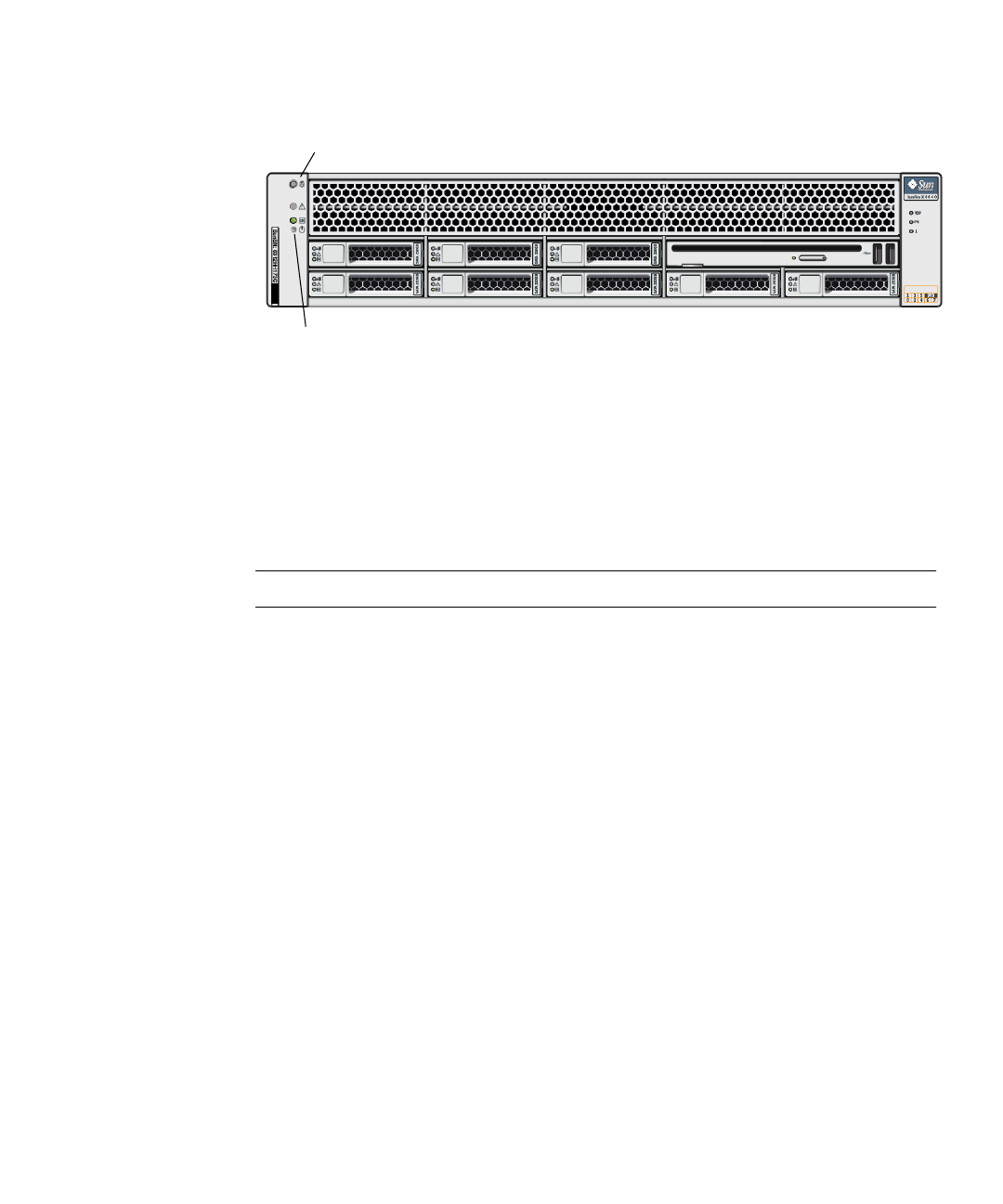
FIGURE 1-2 X4440 Server Front Panel
2. Remove the server cover.
For instructions on removing the server cover, refer to your server’s service
manual.
3. Inspect the internal status indicator LEDs. These can indicate component
malfunction.
For the LED locations and descriptions of their behavior, see “Internal Status
Indicator LEDs” on page 39.
Note – The server must be in standby power mode for viewing the internal LEDs.
You can hold down the Locate button on the server back panel or front panel for
5 seconds to initiate a “push-to-test” mode that illuminates all other LEDs both
inside and outside of the chassis for 15 seconds.
4. Verify that there are no loose or improperly seated components.
5. Verify that all cable connectors inside the system are firmly and correctly
attached to their appropriate connectors.
6. Verify that any after-factory components are qualified and supported.
For a list of supported PCI cards and DIMMs, refer to your server’s service
manual.
7. Check that the installed DIMMs comply with the supported DIMM population
rules and configurations, as described in “DIMM Population Rules” on page 11.
8. Replace the server cover.
9. To restore the server to main power mode (all components powered on), use a
ballpoint pen or other stylus to press and release the Power button on the
server front panel. See
FIGURE 1-1 and FIGURE 1-2.
When main power is applied to the full server, the Power/OK LED next to the
Power button lights and remains lit.
Locate Button/LED
Power Button