


Chapter 5: Advanced Motherboard Setup
5-7
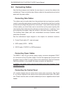
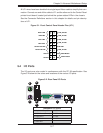
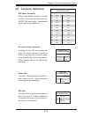
Figure 5-1. Front Control Panel Header Pins (JF1)
All JF1 wires have been bundled into single keyed ribbon cable to simplify their con-
nection. Connect one end of this cable to JF1 and the other end to the Control Panel
printed circuit board, located just behind the system status LEDs in the chassis.
See the Connector Defi nitions section in this chapter for details and pin descrip-
tions of JF1.
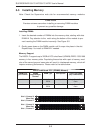
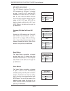
5-4 I/O Ports
The I/O ports are color coded in conformance with the PC 99 specifi cation. See
Figure 5-2 below for the colors and locations of the various I/O ports.
Figure 5-2. Rear Panel I/O Ports
Backplane I/O Ports
1. Keyboard (Purple) 6. COM 1
2. PS/2 Mouse (Green) 7. VGA
3. USB Port 0 8. LAN1
4. USB Port 1 9. LAN2
5. IPMI LAN
Power Button
OH/Fan Fail LED
1
NIC1 LED
Reset Button
2
HDD LED
Power LED
Reset
PWR
LED_Anode+
LED_Anode+
LED_Anode+
UID LED
Ground
Ground
Power Fail LED
NIC2 LED
LED_Anode+
LED_Anode+
1
1
1
9
1
8
1
7
1
6
1
5
1
4
1
3
1
2