


5-14
SUPERSERVER 5017C-MTF/5017C-MTRF User's Manual
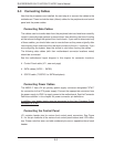
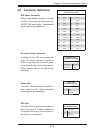
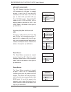
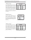
NIC1/NIC2 (LAN1/LAN2)
The NIC (Network Interface Controller)
LED connection for LAN port 1 is located
on pins 11 and 12 of JF1, and the LED
connection for LAN Port 2 is on Pins 9
and 10. NIC1 LED and NIC2 LED are
2-pin NIC LED headers. Attach NIC LED
cables to NIC1 LED and NIC2 LED to
display network activities for LAN 1 and
LAN2. Refer to the table on the right for
pin defi nitions.
LAN1/LAN2 LED
Pin Defi nitions (JF1)
Pin# Defi nition
9/11 Vcc
10/12 LAN Act
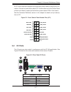
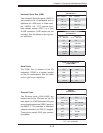
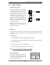
Overheat (OH)/Fan Fail/Front UID
LED
Connect an LED cable to the Front UID
and OH/Fan Fail connections on pins 7
and 8 of JF1 to display UID (Unit ID) sig-
nals or to provide advanced warnings for
chassis overheat/fan failure. Refer to the
table on the right for pin defi nitions.
OH/Fan Fail LED
Pin Defi nitions (JF1)
Pin# Defi nition
7 Vcc/Blue UID LED
8 OH/Fan Fail LED
OH/Fan Fail Indicator
Status
State Defi nition
Off Normal
On Overheat
Flash-
ing
Fan Fail
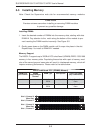
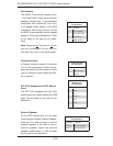
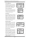
Reset Button
The Reset Button connection is located
on pins 3 and 4 of JF1. Attach it to a the
hardware Reset Button on the computer
case. Refer to the table on the right for
pin defi nitions.
Reset Button
Pin Defi nitions (JF1)
Pin# Defi nition
3 Reset
4 Ground
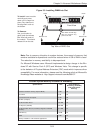
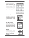
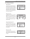
Power Button
The Power Button connection is located
on pins 1 and 2 of JF1. Momentarily
contacting both pins will power on/off the
system. This button can also be confi g-
ured to function as a suspend button (see
BIOS Setup). To turn off the power in the
suspend mode, press the button for at
least 4 seconds. Refer to the table on the
right for pin defi nitions.
Power Button
Pin Defi nitions (JF1)
Pin# Defi nition
1 Signal
2 GND