


Chapter 5: Advanced Motherboard Setup
5-17
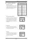
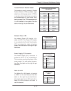
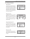
Power Supply I
2
C Connector
The Power Supply (I
2
C) connector is
located at JPI
2
C on the motherboard.
This connector monitors the status of the
power supply, fan and system tempera-
ture. See the table on the right for pin
defi nitions.
PWR Supply I
2
C
Pin Defi nitions
Pin# Defi nition
1 Clock
2 Data
3 PWR Fail
4 Ground
5 3.3V
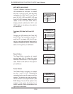
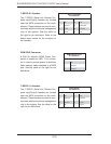
Onboard Power LED
An onboard Power LED header is lo-
cated at JLED. This Power LED header
is connected to the Control Panel header
(JF1) to indicate the status of system
power. See the table on the right for pin
defi nitions.
Onboard PWR LED
Pin Defi nitions
Pin# Defi nition
1 VCC
2 No Connection
3 Connection to PWR
LED in JF1
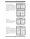
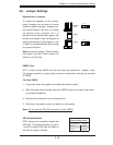
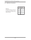
Trusted Platform Module Header
This header is used to connect a Trusted
Platform Module (TPM), available sepa-
rately from a third-party vendor. A TPM is
a security device that allows encryption
and authentication of hard drives, disal-
lowing access if the TPM associated with
it is not installed in the system. See the
table on the right for pin defi nitions.
Trusted Platform Module Header
Pin Defi nitions
Pin # Defi nition Pin # Defi nition
1 LCLK 2 GND
3 LFRAME 4 No Pin
5 LRESET 6 VCC5
7 LAD3 8 LAD2
9 VCC3 10 LAD1
11 LAD0 12 GND
13 RSV0 14 RSV1
15 SB3V 16 SERIRQ
17 GND 18 CLKRUN
19 LPCPD 20 RSV2
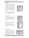
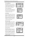
Wake-On-LAN
The Wake-On-LAN header is located
at JWOL on the motherboard. See the
table on the right for pin definitions.
(You must also have a LAN card with a
Wake-On-LAN connector and cable to
use this feature.)
Wake-On-LAN
Pin Defi nitions
(JWOL)
Pin# Defi nition
1 +5V Standby
2 Ground
3 Wake-up