


5-8
S
UPERSERVER 6025B-UR User's Manual
modules of the same size and speed to be installed in pairs. You should not mix
DIMMs of different sizes and speeds.
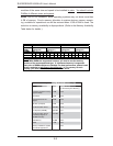
Notes: Due to OS limitations, some operating systems may not show more than
4 GB of memory. Due to memory allocation to system devices, memory remain-
ing available for operational use will be reduced when 4 GB of RAM is used. The
reduction in memory availability is disproportional. (Refer to the Memory Availability
Table below for details.)
Possible System Memory Allocation & Availability
System Device Size Physical Memory Remaining
(4 GB Total System Memory)
Firmware Hub fl ash memory
(System BIOS)
1 MB 3.99
Local APIC 4 KB 3.99
Area Reserved for the
chipset
2 MB 3.99
I/O APIC (4 Kbytes) 4 KB 3.99
PCI Enumeration Area 1 256 MB 3.76
PCI Express (256 MB) 256 MB 3.51
PCI Enumeration Area 2
(if needed) -Aligned on
256-MB boundary-
512 MB 3.01
VGA Memory 16 MB 2.85
TSEG 1 MB 2.84
Memory available to System
BIOS & OS applications
2.84
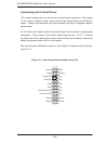
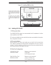
Optimized DIMM Population Configurations
Branch 0 Branch 1
Number of
DIMMs
Bank 1
(Channel 0)
Bank 2
(Channel 1)
Bank 3
(Channel 2)
Bank 4
(Channel 3)
2 DIMMs 1A --- 2A --- --- --- --- ---
4 DIMMs 1A --- 2A --- 3A --- 4A ---
6 DIMMs 1A 1B 2A 2B 3A --- 4A ---
8 DIMMs 1A 1B 2A 2B 3A 3B 4A 4B
Notes: i. “---“ indicates a DIMM slot not to be populated. ii. Both FBD 533 MHz
and 667MHz DIMMs are supported; however, you need to use the memory
modules of the same speed and type. iii. Interleaved memory is supported
when pairs of DIMM modules are installed. For best performance, please install
memory modules in both Branch 0 and Branch 1. iv. For memory to work
properly, you need to follow the restrictions listed above.