


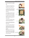
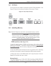
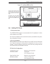

Chapter 5: Advanced Serverboard Setup
5-11
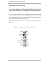
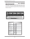
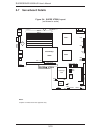
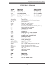
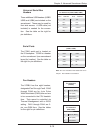
X7DBU Quick Reference
Jumper Description Default Setting
JBT1 CMOS Clear (See Section 5-9)
II
2
C1/II
2
C2 I
2
C Enable/Disable Open (Disabled)
JPG1 VGA Enable/Disable Pins 1-2 (Enabled)
JPL1/ JPL2 JLAN1/JLAN2 Enable/Disable Pins 1-2 (Enabled)
JWD Watch Dog Pins 1-2 (Reset)
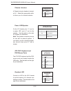
Connector Description
COM1/COM2 COM1/COM2 Serial Port Connector/Header
FAN 1-8 Fan Headers 1-8
Floppy Floppy Disk Drive Connector
IDE#1 IDE Hard Drive Connector
JD1 Power LED (pins1-3)/Speaker Header (pins 4-7)
JF1 Front Control Panel Connector
JL1 Chassis Intrusion Header
JK1 Keylock Header
JOH1 Overheat LED
JPW1 Primary 20-Pin ATX Power Connector
JPW2 Auxiliary Power Connector (4-pin)
JPW3 Processor Power Connector (8-pin)
JWOL Wake-on-LAN Header
JWOR Wake-on-Ring Header
LAN1/2 Gigabit Ethernet Ports
SATA0~SATA5 Intel (ESB2) SATA Ports
SGPIO1/SGPIO2 SGPIO Headers
SIMSO IPMI 2.0 (with virtual media over LAN) Slot
SMB System Management Bus Header
SMBUS_PS System Management (I
2
C) Power Header
USB0/1 USB Ports
USB2/3 USB2/USB3 Header
USB4 USB4 Header
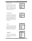
Other Description
LE1 Power On LED
LE2 Rear UID LED
SW1 UID (Unit Identifi er) Button