


2-8
P8SC8/P8SCi User's Manual
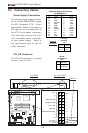
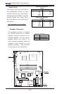
PW_ON Connector
The PW_ON connector is located
on pins 1 and 2 of JF1.
Pin #
1
2
Definition
Signal
+3V Standby
PW_ON
Pin Definitions
(JF1)
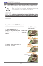
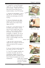
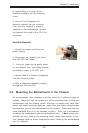
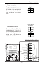
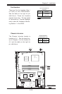
2-6 Connecting Cables
Power Supply Connectors
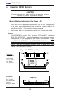
The primary power supply connec-
tor (J1) on the P8SC8/P8SCi meets
the SSI (Superset ATX) 24-pin
specification. Refer to the table on
the right for the pin definitions of
the ATX 24-pin power connector.
You must also connect the 4-pin
(J2) processor power connector
to your power supply. Refer to
the table below right for the J2
(12V) connector.
Pins #
1 & 2
3 & 4
Definition
Ground
+12 V
+12V 4-pin
Connector
(J2)
Required
Connection
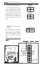
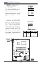
ATX Power Supply 24-pin Connector
Pin Definitions (J1)
Pin Number Definition
13 +3.3V
14 -12V
15 COM
16 PS_ON#
17 COM
18 COM
19 COM
20 Res(NC)
21 +5V
22 +5V
23 +5V
24 COM
Pin Number Definition
1 +3.3V
2 +3.3V
3 COM
4 +5V
5 COM
6 +5V
7 COM
8 PWR_OK
9 5VSB
10 +12V
11 +12V
12 +3.3V
K
B
/M
S
U
S
B
0
/1
C
O
M
1
V
G
A
P
a
ra
lle
l P
o
rt
J
P
U
S
B
1
A
T
X
-2
4
P
in
P
W
R
J
P
F
J
P
W
A
K
E
1
4
-P
in
P
W
R
C
P
U
CopperRiver
NorthBridge
G
L
A
N
1
G
L
A
N
2
D
IM
M
1
A
D
IM
M
1
B
D
IM
M
2
A
DIMM 2B
G
L
A
N
C
T
R
L
G
L
A
N
C
T
R
L
J
P
L
1
J
P
L
2
PCI-X 133/100 MHz
PCI-Ex1
(LGA 775)
SCSI CTRL
7902 W
SCSI Channel A
SCSI Channel B
JW
D
U
S
B
6/7
B
IO
S
JL
1
IDE
Floppy
J5
JB
T
1
JF1
JLED
F
an3
F
an2
JS
LE
D
F
a
n
1
F
a
n
5
Fan4
IC
H
6R
S
outhB
ridge
PXH-V
PCI 33MHz
B
attery
PCI-Ex1
S
A
T
A
3
S
A
T
A
2
S
A
T
A
1
S
A
T
A
0
JW
O
R
JP
A
1
IPMI
COM2
U
S
B
2/3
B
uzzer
W
O
L
J
B
T
1
J9
JSLED
L
E
1
E7221
KB/MS
1
ATX-24 Pin PWR
P
F
JPWAKE1
4-Pin
Fan1
Fan5
ATX PWR 12V 4-Pin PWR
NIC1 LED
Power Butto
n
O
verheat/Fan Fail LED
1
Reset Butto
n
2
IDE/SATA LED
Power On LED
Reset
Signal
Vcc
Vcc
Vcc
Vcc
Ground
3V Standby
1920
Vcc
X
Ground
NMI
X
X
X
NIC2 LED
PWR-On