


2-18
P8SC8/P8SCi User's Manual
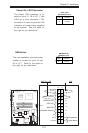
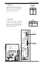
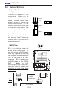
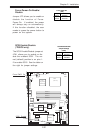
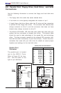
CMOS Clear
JBT1 is not actually a jumper but
consists of two contact pads. To
clear the contents of CMOS, short
these pads together by touching
them both with a metal conductor
such as the head of a small
screwdriver. JBT1 is located near
the SATA header on the P8SC8/
P8SCi. Note: for ATX
power supplies, you must com-
pletely shut down the system and
remove the AC power cord before
clearing CMOS.
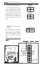
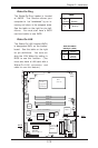
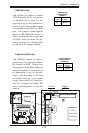
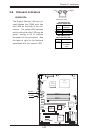
2-7 Jumper Settings
Explanation of
Jumpers
To modify the operation of the
motherboard, jumpers can be
used to choose between optional
settings. Jumpers create shorts
between two pins to change the
function of the connector. Pin 1 is
identified with a square solder pad
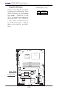
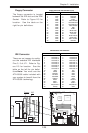
on the printed circuit board. See
the motherboard layout pages for
jumper locations.
Note: On a two-pin jumper,
"Closed" means the jumper is on
both pins and "Open" means the
jumper is either on only one pin or
completely removed.
Connector
Pins
Jumper
Cap
Setting
Pin 1-2 short
3 2 1
3 2 1
K
B
/M
S
U
S
B
0
/1
C
O
M
1
V
G
A
P
a
ra
lle
l P
o
rt
J
P
U
S
B
1
A
TX
-24 P
in P
W
R
J
P
F
J
P
W
A
K
E
1
4-P
in
PW
R
C
P
U
CopperRiver
NorthBridge
G
LA
N
1
G
LA
N
2
D
IM
M
1A
D
IM
M
1B
D
IM
M
2A
DIMM 2B
G
LA
N
C
TR
L
G
LA
N
C
TR
L
J
P
L
1
J
P
L
2
PCI-X 133/100 MHz
PCI-Ex1
(L
G
A
7
7
5
)
SCSI CTRL
7902 W
S
C
S
I C
hannel A
SCSI Channel B
JWD
USB6/7
BIOS
JL1
ID
E
Floppy
J5
JBT1
JF1
J
L
E
D
Fan3
Fan2
JSLED
Fan1
Fan5
Fan4
ICH6R
SouthBridge
PXH-V
PCI 33MHz
Battery
PCI-Ex1
SATA3
SATA2
SATA1
SATA0
JWOR
JPA1
IP
M
I
C
O
M
2
USB2/3
Buzzer
WOL
J
B
T
1
J9
J
S
L
E
D
LE1
E7221
CTRL
JPL1
JPL2
l
B
BIOS
JBT1
ICH6R
SouthBridge
PCI 33MHz
Ba
t
JBT1
Clear
CMOS