


Chapter 2: Installation
2-11
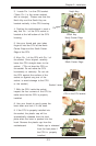
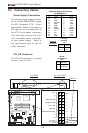
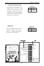
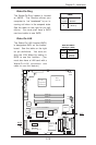
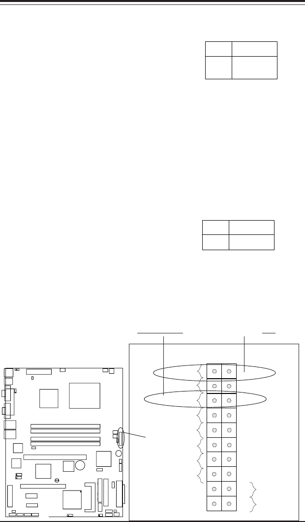
Power On_LED Connector
The Power LED connector is lo-
cated on pins 15, 16 of JF1. (*Use
JLED for a 3-pin connector.) This
connection is used to provide LED
indication of power being supplied
to the system. See the table on
the right for pin definitions.
Pin
Number
15
16
Definition
+5V
Ground
Power_LED
Pin Definitions (JF1)
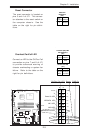
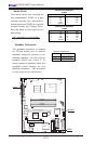
NMI Button
The non-maskable interrupt button
header is located on pins 19 and
20 of JF1. Refer to the table on
the right for pin definitions.
Pin
Number
19
20
Definition
Control
Ground
NMI Button Pin
Definitions (JF1)
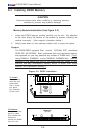
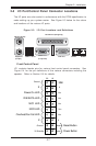
NIC1 LED
Power Butto
n
O
verheat/Fan Fail LED
1
Reset Butto
n
2
IDE/SATA LED
Power On LED
Reset
Signal
Vcc
Vcc
Vcc
Vcc
Ground
3V Standby
1920
Vcc
X
Ground
NMI
X
X
X
NIC2 LED
KB/MS
USB0/1
COM1
VGA
Parallel Port
JPUSB1
ATX-24 Pin PWR
JPF
JPWAKE1
4-Pin
PWR
CPU
CopperRiver
NorthBridge
GLAN1
GLAN2
DIMM 1A
DIMM 1B
DIMM 2A
DIMM 2B
GLAN
CTRL
GLAN
CTRL
JPL1
JPL2
PCI-X 133/100 MHz
PCI-Ex1
(L
G
A
7
7
5
)
SCSI CTRL
7902 W
S
C
S
I C
h
a
n
n
e
l A
SCSI Channel B
J
W
D
U
S
B
6
/7
B
IO
S
J
L
1
ID
E
F
lo
p
p
y
J
5
J
B
T
1
J
F
1
J
L
E
D
F
a
n
3
F
a
n
2
J
S
L
E
D
Fan1
Fan5
Fan4
IC
H
6
R
S
o
u
th
B
rid
g
e
PXH-V
PCI 33MHz
B
a
tte
ry
PCI-Ex1
S
A
T
A
3
S
A
T
A
2
S
A
T
A
1
S
A
T
A
0
J
W
O
R
J
P
A
1
IP
M
I
C
O
M
2
U
S
B
2
/3
B
u
z
z
e
r
W
O
L
JBT1
J
9
J
S
L
E
D
LE1
E7221
NMIPWR-On LED