


ix
List of Figures
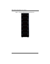
Figure 1-1. Full Rack of Blade Enclosures and Blade Servers .........................1-4
Figure 3-1. Inserting a Blade into the Enclosure...............................................3-3
Figure 3-2. Locking the Blade into Position.......................................................3-3
Figure 3-3. Installing a G34 Processor in a Socket...........................................3-5
Figure 3-4. Installing the Onboard Battery........................................................3-6
Figure 3-5. 8-Slot DIMM Numbering for Two Node Blade Modules..................3-7
Figure 3-6. Installing a DIMM into a Memory Slot.............................................3-8
Figure 3-7. Installing a Hard Drive in a Carrier................................................3-10
Figure 4-1. SBA-7222G-T2 Blade Unit Front View ...........................................4-1
Figure 4-2. Blade Control Panel........................................................................4-2
Figure 4-3. BHDGT Mainboard.........................................................................4-4
Figure 4-4. BHDGT Block Diagram...................................................................4-6
Figure 4-5. Exploded View of SBA-7222G-T2 Blade Module ...........................4-7
Figure 5-1. IDE Configuration Screen – Configure RAID Drives.......................5-2
Figure 5-2. Exit BIOS Setup..............................................................................5-3
Figure 5-3. Screen Message.............................................................................5-4