


B-4
SCF418 Chassis Manual
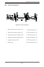
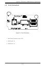
5 Upgrade Connector
The upgrade connector, designated JP46 is a
rmware upgrade port.
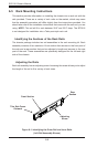
Backplane
Main Power
4-Pin Connector
Pin# Denition
1 and 2 Ground
3 +5V
4 +12V
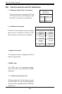
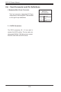
B-6 Front Connector and Pin Denitions
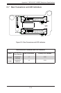
1 - 2 Backplane Main Power Connectors
The 4-pin connectors, designated JP10 and
JP13 provide power to the backplane. See
the table on the right for pin denitions.
6 ATMEL Chip
The ATMEL chip is an enclosure manage-
ment chip used in the BPN-SAS-F418-B6
backplane.
3 - 4 Sideband Connectors
For SES-2 to work properly, an 8-pin sideband
cable must be connected to JP52 and JP54.
See the table to the right for pin denitions.
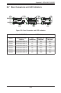
Sideband Connector
Pin # Denition Pin # Denition
2 Backplane
Addressing
(SB5)
1 Controller
ID (SB6)
4 Reset (SB4) 3 GND (SB2)
6 GND (SB3) 5 SDA (SB1)
8 Backplane
ID (SB7)
7 SCL (SB0)
10 No Connec-
tion
9 No Connec-
tion
7 - 11 SATA Connectors #0 - #5
SATA connectors #0 - #5 are used to connect
the SATA cables. The six ports are designated
#0 - #5 and are compatible with both SAS and
SATA drives.