


Chapter 2: Installation
2-5
Installation
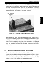
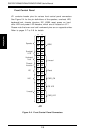
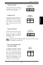
Top View of DIMM Slot
To Remove:
Use your thumbs to gently push near the edge of both ends of
the module. This should release it from the slot.
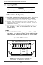
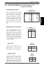
2-5 Port/Control Panel Connector Locations
The I/O ports are color coded in conformance with the PC 99 specification.
See Figure 2-3 below for the colors and locations of the various I/O ports.
Parallel Port
(Burgundy)
Game Port
(Gold)
COM1 Port
(Turquoise)
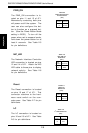
Keyboard
(Purple)
Mouse
(Green)
USB
Ports
(Black)
Figure 2-3. I/O Port Locations and Definitions
Ethernet
Port
(Black)
Line Out Line In Mic
(Lime) (Light blue) (Pink)