


Chapter 2: Installation
2-11
Installation
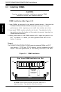
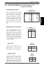
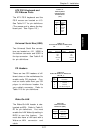
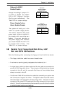
Universal Serial Bus (USB)
Two Universal Serial Bus connec-
tors are located on J12. USB0 is
the bottom connector and USB1 is
the top connector. See Table 2-18
for pin definitions.
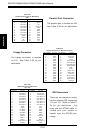
Table 2-18
Universal Serial Bus Pin Definitions
Pin
Number Definition
1 +5V
2 P0-
3 P0+
4 Ground
5 N/A
Pin
Number Definition
1 +5V
2 P0-
3 P0+
4 Ground
5 Key
J12
J12
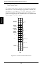
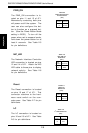
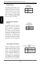
ATX PS/2 Keyboard and
PS/2 Mouse Ports
The ATX PS/2 keyboard and the
PS/2 mouse are located on J13.
See Table 2-17 for pin definitions.
(The mouse port is above the key-
board port. See Figure 2-3.)
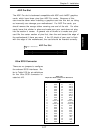
Table 2-17
PS/2 Keyboard
and Mouse Port
Pin Definitions
(J13)
Pin
Number
1
2
3
4
5
6
Definition
Data
NC
Ground
VCC
Clock
NC
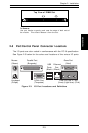
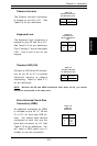
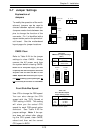
CD Headers
There are two CD headers of dif-
ferent sizes on the motherboard to
enable audio CD playback. Con-
nect an audio cable from your CD
player to whichever header fits
your cable's connector. Refer to
Table 2-19 for pin definitions.
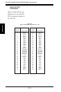
Table 2-19
Audio CD Header Pin Definitions
(CD, CD_1)
Pin
Number
1
2
3
4
Definition
Right Stereo Signal
Ground
Ground
Left Stereo Signal
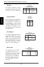
Pin
Number
1
2
3
Definition
+5V Standby
Ground
Wake-up
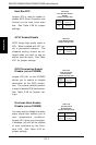
Table 2-20
Wake-On-LAN Pin
Definitions (WOL)
Wake-On-LAN
The Wake-On-LAN header is des-
ignated as WOL. Refer to Table 2-
20 for pin definitions. You must
enable the LAN Wake-Up setting in
BIOS to use this feature. You
must also have a LAN card with a
Wake-on-LAN connector and
cable.