


Chapter 2: Installation
2-7
Installation
2-6 Connecting Cables (see previous page for JF1
connection locations)
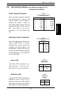
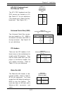
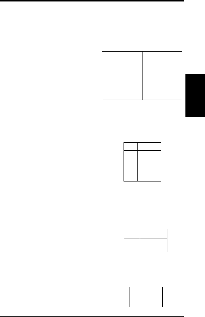
Power Supply Connector
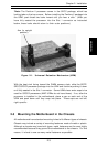
After you have securely mounted
the motherboard, memory and
add-on cards, you are ready to
connect the cables. Attach an
ATX power supply cable to J27 by
aligning the tabs on both connec-
tors. See Table 2-1 for the pin
definitions of an ATX power sup-
ply.
Table 2-1
ATX Power Supply Connector
Pin Definitions (J27)
Pin Number Definition
1 3.3V
2 3.3V3
3 Ground
45V
5 Ground
65V
7 Ground
8 PW-OK
9 5VSB
10 12V
Pin Number Definition
11 3.3V
12 -12V
13 Ground
14 PS-ON
15 Ground
16 Ground
17 Ground
18 -5V
19 5V
20 5V
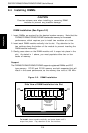
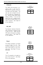
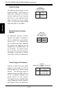
Secondary Power Connector
Use of the Secondary Power con-
nector (PWR_SEC) is recom-
mended when a heavy load of pe-
ripherals has been added to the
motherboard.
Note: Be sure to use a 6-
pin connector and check the power supply lay-
out before attaching it.
See Table 2-2
for pin definitions.
Table 2-2
Secondary Power Connector
(PWR_SEC)
Pin
Number Definition
1 Ground
2 Ground
3 Ground
4 +3.3V
5 +3.3V
6 +5V (keyed)
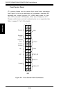
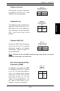
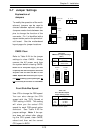
Power LED
The Power LED connection is lo-
cated on pins 1, 3 and 5 of JF1.
See Table 2-6 for pin definitions.
Pin
Number
1
3
5
Definition
+5V
Key
GND
Table 2-3
PWR_LED Pin
Definitions (JF1)
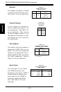
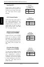
Table 2-4
IDE_LED Pin
Definitions
(JF1)
Pin
Number
7
9
Definition
+5V
HD Active
Hard Drive LED
The Hard Drive LED connection is
located on pins 7 and 9 of JF1.
Attach the hard drive LED cable to
these pins to display disk activity.
See Table 2-5 for pin definitions.