


2-8
SUPER PIIIDM6/PIIIDM4/PIIIDM3/PIIIDME User's Manual
Installation
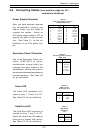
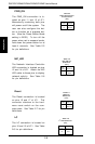
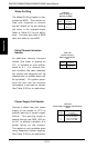
PWR_ON
The PWR_ON connection is lo-
cated on pins 11 and 13 of JF1.
Momentarily contacting both pins
will power on/off the system. The
user can also configure this but-
ton to function as a suspend but-
ton. (See the Power Button Mode
setting in BIOS.) To turn off the
power when set to suspend mode,
hold down the power button for at
least 4 seconds. See Table 2-5
for pin definitions.
Pin
Number
11
13
Definition
PW_ON
Ground
Table 2-5
PWR_ON Connector
Pin Definitions
(JF1)
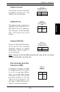
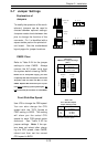
Reset
The Reset connection is located
on pins 15 and 17 of JF1. This
connector attaches to the hard-
ware reset switch on the com-
puter case. See Table 2-7 for pin
definitions.
Pin
Number
15
17
Definition
Reset
Ground
Table 2-7
Reset Pin
Definitions
(JF1)
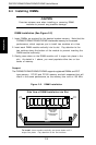
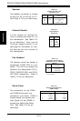
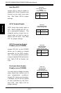
NIC_LED
The Network Interface Controller
LED connection is located on pins
12 and 14 of JF1. Attach the NIC
LED cable to these pins to display
network activity. See Table 2-6
for pin definitions.
Table 2-6
NIC_LED Pin
Definitions
(JF1)
Pin
Number
12
14
Definition
+5V
GND
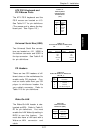
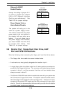
I
2
C
The I
2
C connection is located on
pins 16 and 18 of JF1. See Table
2-6 for pin definitions.
Table 2-8
I
2
C Pin Definitions
(JF1)
Pin
Number
16
18
Definition
SDA
SCL