


SUPER X5DL8-GG/X5DLR-8G2+/X5DLR-8G2 User’s Manual
1-6
Introduction
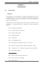
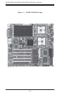
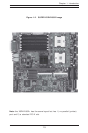
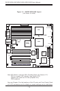
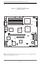
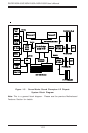
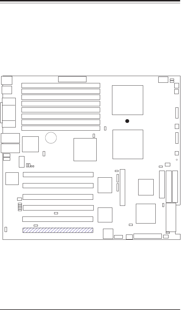
Figure 1-3. SUPER X5DL8-GG Layout
(not drawn to scale)
Note:DIP Switch 4 sets the CPU Core/Bus Ratio (see Section 2-7).
CR5 is a power LED indicator (see Section 2-6).
Jumpers not noted are for test purposes only.
IPMI is optional.
Also see Chapter 2 for the locations of the I/O ports and Front Control Panel
(JF1/JF2) connectors and for details on jumper settings and pin definitions.
J11
Keyboard/Mouse
J66
ATX POWER
GLAN1
USB0/1
Rage XL
J55
COM1
VGA
GLAN2
CPU1
CPU2
North
Bridge
BATTERY
J56
Bank 1A
Bank 1B
Bank 2A
Bank 2B
Bank 3A
Bank 3B
Bank 4A
Bank 4B
Parallel
Port
J65
D5-D8
COM2
D1-D4
South
Bridge
Broadcom
Controller
SUPER X5DL8-GG
®
J12
J19
J18
IDE #2
IDE #1
FLOPPY
PCI-X #6
PCI-X #5
PCI-X #4
PCI-X #1
PCI-X #2
PCI-X #3
BIOS
AIC-7902
Ultra III LVD/SE ChB
IPMI
JP54
SW4
Ultra III LVD/SE ChA
IO Bridge
JF1
CPU2/CHS FAN
CPU2 FAN
CPU1 FAN
CPU1/CHS FAN
OH/CHS FAN
JF2
IO Bridge
JP48
JP7
JP4
JP56
JBT1
S1
P1
P2
S2
WOL
JP2
J29
J1
JA4
JPA1
CHS FAN
JPA2
CR5
JP58
JP57
J35
J20
J21
JP3
JA2
JA1
JP12