


2-2
SUPER X5DL8-GG/X5DLR-8G2+/X5DLR-8G2 User’s Manual
IMPORTANT: Always connect the power cord last and always remove it
before adding, removing or changing any hardware components. Make
sure that you install the processor into the CPU socket before you install
the CPU heat sink. Note: pictures show 603-pin socket.
!
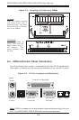
2-2 PGA Processor and Heatsink Installation
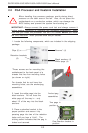
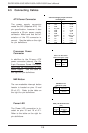
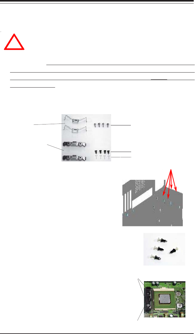
1. Locate the following components, which are included in the shipping
package.
Retention brackets
(2)
Clips (2)
Screws* (4)
*These screws are for mounting the
motherboard to the back panel of a
chassis that has four mounting holes
(as shown on right).
White pegs (4)
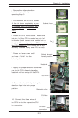
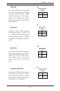
2. Insert the white pegs into the
black anchors. Do not force the
white pegs all the way in - only
about 1/3 of the way into the black
anchors.
3. Place a retention bracket in the
proper position and secure it by
pressing pegs into two of the retention
holes until you hear a *click*. The
clicking sound indicates that the peg is
locked and secured.
Two pegs in
position
One retention bracket in
position
Black anchors (4)
For chassis that do not have four
mounting holes, use the anchor/peg
assemblies:
Anchor/peg
assemblies
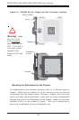
When handling the processor package, avoid placing direct
pressure on the label area of the fan. Also, do not place the
motherboard on a conductive surface, which can damage the
BIOS battery and prevent the system from booting up.