


Chapter 3: Installation
3-21
X8DTU-6F+
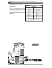
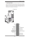
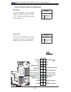
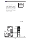
Front Control Panel
JF1 contains header pins for various buttons and indicators that are normally lo-
cated on a control panel at the front of the chassis. These connectors are designed
specifi cally for use with Supermicro server chassis. See the fi gure below for the
descriptions of the various control panel buttons and LED indicators. Refer to the
following section for descriptions and pin defi nitions.
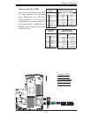
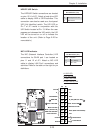
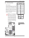
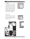
JF1 Header Pins
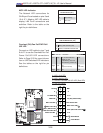
Power Button
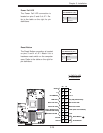
Blue+ (OH/Fan Fail/
PWR FaiL/UID LED
1
NIC1 Link LED
Reset Button
2
Power Fail LED
HDD LED
FP PWRLED
Reset
PWR
3.3 V
ID_UID_SW/3/3V Stby
Red+ (Blue Led Cathode)
Ground
Ground
1920
3.3V
X
Ground
NMI
X
NIC2 Link LED
NIC2 Active LED
NIC1 Active LED