


Chapter 3: Installation
3-25
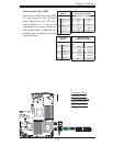
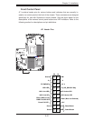
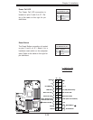
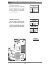
Power Button
Blue+ (OH/Fan Fail/
PWR FaiL/UID LED
1
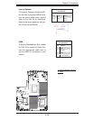
NIC1 Link LED
Reset Button
2
Power Fail LED
HDD LED
FP PWRLED
Reset
PWR
3.3 V
ID_UID_SW/3/3V Stby
Red+ (Blue Led Cathode)
Ground
Ground
1920
3.3V
X
Ground
NMI
X
NIC2 Link LED
NIC2 Active LED
NIC1 Active LED
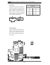
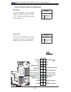
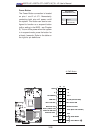
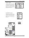
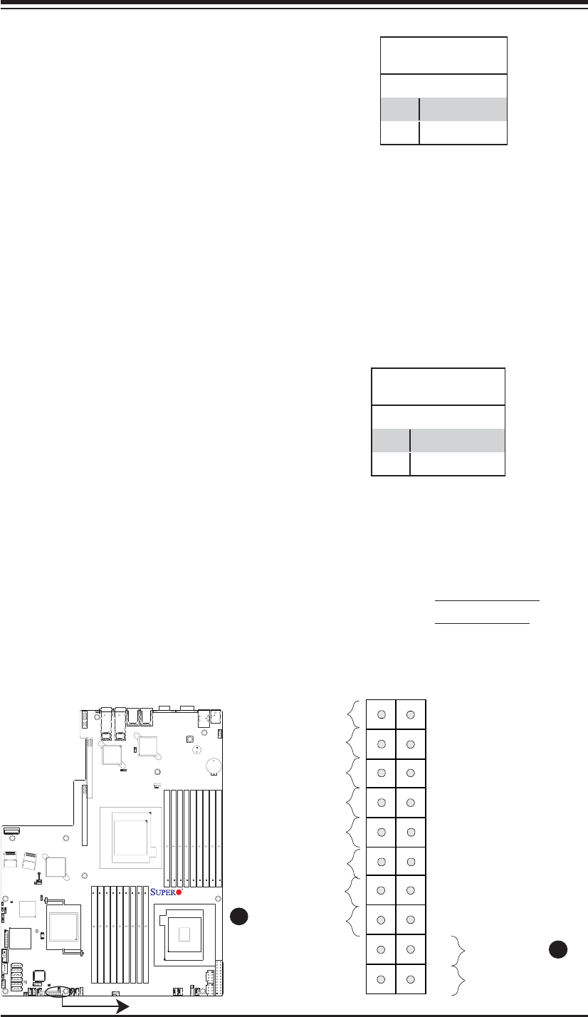
Power Fail LED
The Power Fail LED connection is
located on pins 5 and 6 of JF1. Re-
fer to the table on the right for pin
defi nitions.
PWR Fail LED
Pin Defi nitions (JF1)
Pin# Defi nition
5 3.3 V
6 Ground
X8DTU-6F+
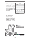
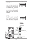
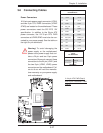
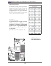
Reset Button
The Reset Button connection is located
on pins 3 and 4 of JF1. Attach it to a
hardware reset switch on the computer
case. Refer to the table on the right for
pin defi nitions.
Reset Button
Pin Defi nitions (JF1)
Pin# Defi nition
3 Reset
4 Ground
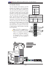
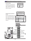
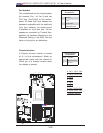
A. PWR Fail LED
B. Reset Button
A
B