


Chapter 2: Installation
2-17
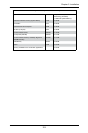
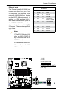
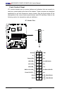
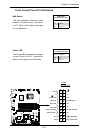
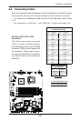
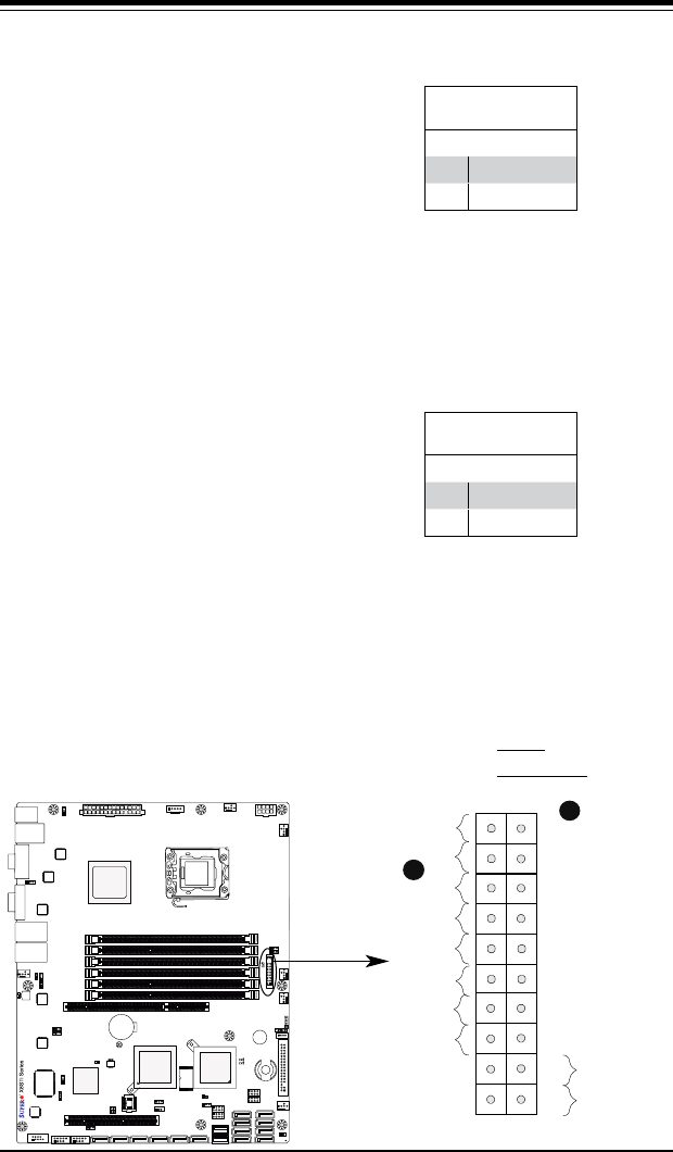
FrontControlPanelPinDenitions
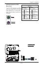
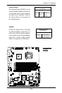
Power LED
The Power LED connection is located
on pins 15 and 16 of JF1. Refer to the
table on the right for pin denitions.
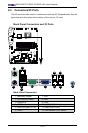
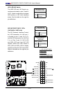
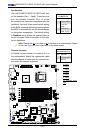
NMI Button
The non-maskable interrupt button
header is located on pins 19 and 20
of JF1. Refer to the table on the right
for pin denitions.
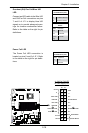
Power Button
OH/Fan Fail LED
1
NIC1 LED
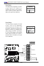
Reset Button
2
Power Fail LED
HDD LED
Power LED
#3~4
#1~2
Vcc
Vcc/UID Switch
Vcc
Vcc/Blue UID LED
Ground
Ground
1920
Vcc
X
Ground
NMI
X
Vcc
NIC2 LED
NMI Button
PinDenitions(JF1)
Pin# Denition
19 Control
20 Ground
Power LED
PinDenitions(JF1)
Pin# Denition
15 +5V
16 Ground
A. NMI
B. PWR LED
A
B