


2-22
X8STi/X8STi-F/X8STi-3F/X8STi-LN4 User's Manual
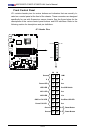
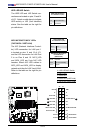
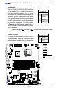
LSI 1068E
NIC4 LED
JBMC1
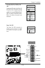
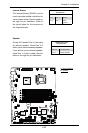
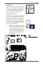
Fan Header
PinDenitions
Pin# Denition
1 Ground (Black)
2 2.5A/+16V
(Red)
3 Tachometer
4 PWM_Control
Fan Headers
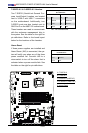
The X8STi/X8STi-F/X8STi-3F/X8STi-LN4 has
six fan headers (Fan1 ~ Fan6). These fans are
4-pin fan headers. However, Pins 1-3 of the
fan headers are backward compatible with the
traditional 3-pin fans. A fan speed control setting
in the BIOS Hardware Monitoring section allows
the BIOS to automatically set fan speeds based
on the system temperature. The default setting
is Disabled which allows the onboard fans to
run at full speed. Refer to the table on the right
for pin denitions.
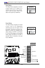
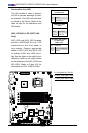
A
B
A. Fan1
B. Fan2
C. Fan3
D. Fan4
E. Fan5
F. Fan6
G. Chassis Intru-
sion
C
D
E
F
G
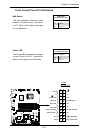
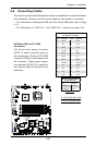
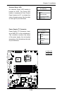
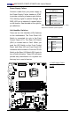
Chassis Intrusion
A Chassis Intrusion header is located at JL1 on
the motherboard. Attach the appropriate cable
from the chassis to inform you of a chassis intru-
sion when the chassis is opened.
Chassis Intrusion
PinDenitions(JL1)
Pin# Denition
1 Intrusion Input
2 Ground
Note: Please use all 3-pin fans or all 4-pin fans on a motherboard. Please
do not use 3-pin fans and 4-pin fans on the same board.