3-5
Maintenance and Specifications
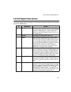
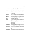
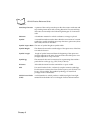
LS 2100 Signal Descriptions
The following signal descriptions apply to the connection between the scanner and the cable,
and are for reference only.
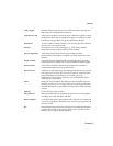
Pin Signal Name Function
2Power This pin is to be connected to the 4.75 to 14 V (4.75 to 14
VDC) power supply. When pin 4 is high, current to operate
the scanner is supplied by pin 1,2 (99 mA @ 5 VDC).
When pin 4 is at ground potential, current into pin 1 and
2 is less than 50 µA.
3 Ground Power supply and signal ground return line.
4Enable When the decode logic senses that the trigger has been
pulled, this input must be driven high (+2.4 to +14 V into
a 10 kilohm load) to power-up the scanner electronics and
turn on the laser and resonating harmonic scan element.
As soon as a decode is successfully completed, if no decode
occurs after about 1 second, or when the trigger is
released, this input should float or be driven to ground
(less than 0.4 V) to power-down the scanner.
5 Start of Scan This output synchronizes the decode logic with the
scanner. The output is high when the beam sweeps in one
direction and low when it sweeps in the opposite direction.
This open collector signal is capable of sinking 25 mA. An
external pullup resistor may be connected to any voltage
up to 20 V. The frequency of scans is 36 scans/sec.
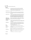
6 Trigger Switch This output is grounded when the trigger is pulled and
floating when the trigger is released. The decode logic uses
this switch to signal that the operator wishes to read a bar
code.
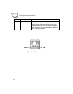
7 Decode LED This input to the scanner controls the green decode
indicator LED and sounds the beeper. Applying a voltage
of 2.5 V or greater will light the LED. Maximum voltage
that can be applied to this input is 15 V. This current
decreases as the voltage is lowered. The decode LED can
be activated with this input even when the scanner is not
operating, providing power is present at pin 2.


