


2121
2121
21
2.8 Jumpers Setup2.8 Jumpers Setup
2.8 Jumpers Setup2.8 Jumpers Setup
2.8 Jumpers Setup
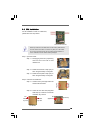
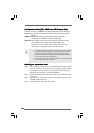
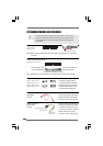
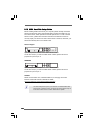
The illustration shows how jumpers are
setup. When the jumper cap is placed on
pins, the jumper is “Short”. If no jumper cap
is placed on pins, the jumper is “Open”. The
illustration shows a 3-pin jumper whose pin1
and pin2 are “Short” when jumper cap is
placed on these 2 pins.
Jumper Setting Description
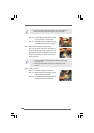
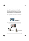
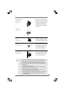
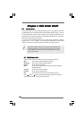
PS2_USB_PWR1 Short pin2, pin3 to enable
(see p.10 No. 1) +5VSB (standby) for PS/2
or USB wake up events.
Note: To select +5VSB, it requires 2 Amp and higher standby current provided by
power supply.
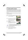
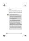
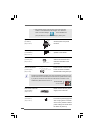
Clear CMOS
(CLRCMOS1, 2-pin jumper)
(see p.10 No. 6)
Note: CLRCMOS1 allows you to clear the data in CMOS. The data in CMOS includes
system setup information such as system password, date, time, and system
setup parameters. To clear and reset the system parameters to default setup,
please turn off the computer and unplug the power cord from the power
supply. After waiting for 15 seconds, use a jumper cap to short 2 pins on
CLRCMOS1 for 5 seconds.
+5V
1_2
+5VSB
2_3
2-pin jumper