83-493-001 Rev. K
9
CHAPTER 3 INSTALLATION
3.1 INITIAL INSPECTION
The shipping container should contain the following items: power supply, HV output
cable, male 15-pin “D” remote control connector and operator’s manual. Examine the
items immediately for damage. Locate the serial number label on the side of the power
supply and verify the model number, the input voltage rating and the output voltage
rating and polarity. In the event of any damage promptly notify the transportation
company and the TDK-Lambda Americas Inc. Customer Service Department.
3.2 MOUNTING AND COOLING REQUIREMENTS
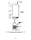
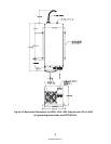
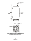
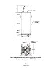
The power supply can be mounted by the chassis support brackets (see Figure 2-1, 2-2,
2-3 and 2-4 for details). The mounting brackets are attached to the supply. The supply
must be mounted using four PHMS 8-32NC X 0.250 screws. Using wrong (longer)
screws may short HV parts to ground, causing permanent damage to power supply. The
power supply can also operate on a bench or table top. Power supplies >6kV with Oil
H.V. section must be operated in upright position i.e. mounting bracket parallel to ground
plane. In all cases adequate clearances must be provided for proper air flow and cable
bends. Keep the minimum HV cable bend radius greater than 4 inches (101.6mm) to
minimize stress on the insulation. Generally, at least 4 inches (101.6mm) of clearance
should be allowed at the inlet of the power supply and 2 inches (50.8mm) at the sides.
When operating in an enclosed system, care must be taken to ensure the ambient inlet
air to the power supply does not exceed the maximum operating temperature of 45ºC.
This often requires addition of a system heat exchanger.
3.3 INPUT AC POWER
Proper grounding from the input AC power is required to reduce the risk of electric
shock. The metal chassis of the power supply is grounded through the green earthing
wire at the input AC power terminal block. A protective ground connection by way of the
grounding conductor in the input terminal is essential for safe operation. Use extreme
caution when connecting input AC power and never apply the incorrect input power.
(Figure 2-1, 2-2, 2-3 & 2-4).
The PFC version and version without PFC should be connected as explained in the
following 2 paragraphs.
A.. Version with no PFC.
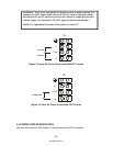
For this version, the supply can be connected to either 115VAC for 230VAC input
voltage (See table 2.2). These connections are shown in Figure 3-1.
For 115VAC connect the input line wires to L1 and COM terminals.
For 230VAC connect the input wires to L2 and COM terminals.
B. Version with PFC.
The PFC version connection is shown in Figure 3-2. Connect the input voltage line wires
to L2 and COM terminals.


