83-493-001 Rev. K
17
A series terminating resistor (or series inductor or clamp diode) must be added as shown
if the average value of the peak current exceeds 110% of the normal output current.
When choosing Rs, ensure it can withstand the full output voltage across it as well as
the power dissipation caused by discharging Co (see Table 5.1) and Cc (20pF/ft) (65.62
pf/m) each cycle as well as conducting the normal output current. It’s power dissipation
can be calculated as Pd = (Io² Rs) + ½ (Co + Cc) V² (REP RATE).
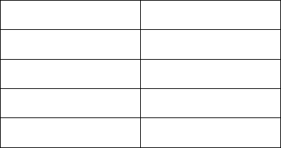
Output Voltage Co
1-2.8kV 60nF
3kV-6kV 15nF
10-30kV 460pF
40kV 230pF
Table 5-1 Output Capacitance
5.3 PARALLELING UNITS
The 500A/102A/152A/202A power supplies are designed for simple parallel operation.
The input power and HV output should be connected directly together. The REMOTE
connectors on the input panel can also be connected directly together using a “daisy
chain” ribbon cable from the system controller. Each of the power supplies operate at the
same time with the total charge rate equal to the sum of each.
Sometimes when operating several units in parallel, the high total power generates noise
which interferes with the power supply control. This is usually due to the many
interconnecting control cables acting as an antenna picking up noise. The problem
usually appears as one or more of the power supplies shuts down when the output
voltage increases beyond a certain level. Dressing the control cables as short as
possible and close to ground or using shielded cables should help. In severe cases, it is
necessary to wrap the cables several times through high permeability ferrite cores at the
input panel of each unit.
The 500A/102A/152A/202A power supplies can also be used as an Isolated High
Voltage continuous DC power source by adding an external filter capacitor. The value of
the filter capacitor depends upon the value of the allowable output voltage ripple value.
For parallel operation into DC loads, please contact TDK-Lambda Americas Inc.
Customer Service Department. (See Section 5.6).


