


Advanced Data Sheet: Veta
iHA48060A012V*, 1.2V/60A Output Half Brick
Series
©2007
TDK Innoveta Inc.
iHA Datasheet 040207
'
(877) 498
-
0099
12
/
16
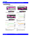
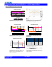
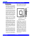
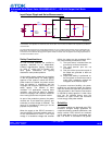
Heat transfer by convection can be
enhanced by increasing the airflow rate that
the power module experiences. The
maximum output current of the power
module is a function of ambient temperature
(T
AMB
) and airflow rate as shown in the
thermal performance figures on the thermal
performance page for the power module of
interest. The curves in the figures are shown
for natural convection through 3 m/s (600
ft/min). The data for the natural convection
condition has been collected at 0.3 m/s (60
ft/min) of airflow which is the typical airflow
generated by other heat dissipating
components in many of the systems that
these types of modules are used in. In the
final system configurations, the airflow rate
for the natural convection condition can vary
due to temperature gradients from other
heat dissipating components.
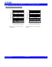
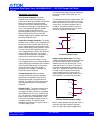
Heatsink Usage: For applications with
demanding environmental requirements,
such as higher ambient temperatures or
higher power dissipation, the thermal
performance of the power module can be
improved by attaching a heatsink or cold
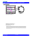
plate. The iHx platform is designed with a
base plate with four M3 X 0.5 through-
threaded mounting fillings for attaching a
heatsink or cold plate. The addition of a
heatsink can reduce the airflow requirement
and ensure consistent operation and
extended reliability of the system. With
improved thermal performance, more power
can be delivered at a given environmental
condition.
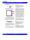
Standard heatsink kits are available from
TDK Innoveta for vertical module mounting
in two different orientations (longitudinal –
perpendicular to the direction of the pins and
transverse – parallel to the direction of the
pins). The heatsink kit contains four M3 x
0.5 steel mounting screws and a precut
thermal interface pad for improved thermal
resistance between the power module and
the heatsink. The screws should be installed
using a torque-limiting driver set between
0.35 and 0.55 Nm (3-5 in-lbs).
During heatsink assembly, the base-plate to
heatsink interface must be carefully
managed. A thermal pad may be required
to reduce mechanical-assembly-related
stresses and improve the thermal
connection. Please contact TDK Innoveta
Engineering for recommendations on this
subject.
The system designer must use an accurate
estimate or actual measurement of the
internal airflow rate and temperature when
doing the heatsink thermal analysis. For
each application, a review of the heatsink fin
orientation should be completed to verify
proper fin alignment with airflow direction to
maximize the heatsink effectiveness. With
respect to TDK Innoveta standard heatsinks,
contact TDK Innoveta for the latest
performance data.