


Advanced Data Sheet: Veta
iHA48060A012V*, 1.2V/60A Output Half Brick
Series
©2007
TDK Innoveta Inc.
iHA Datasheet 040207
'
(877) 498
-
0099
13
/
16
Operating Information:
Over-Current Protection: The power
modules have current limit protection to
protect the module during output overload and
short circuit conditions. During overload
conditions, the power modules may protect
themselves by entering a hiccup current limit
mode. The modules will operate normally
once the output current returns to the
specified operating range. There is a typical
delay of 2mS from the time an overload
condition appears at the module output until
the hiccup mode will occur.
Output Over-Voltage Protection: The power
modules have a control circuit, independent of
the primary control loop that reduces the risk
of over voltage appearing at the output of the
power module during a fault condition. If there
is a fault in the primary regulation loop, the
over voltage protection circuitry will cause the
power module to shut down. The module
remains off unless either the input power is
recycled or the on/off switch is toggled.
The iHA Veta
family also offers a hiccup
over-voltage protection once it detects that the
output voltage has reached the level indicated
in the Electrical Data section for the power
module of interest. When the condition
causing the over-voltage is corrected, the
module will operate normally.
Thermal Protection: When the power
modules exceed the maximum operating
temperature, the modules may turn-off to
safeguard the power unit against thermal
damage. The module will auto restart as the
unit is cooled below the over temperature
threshold.
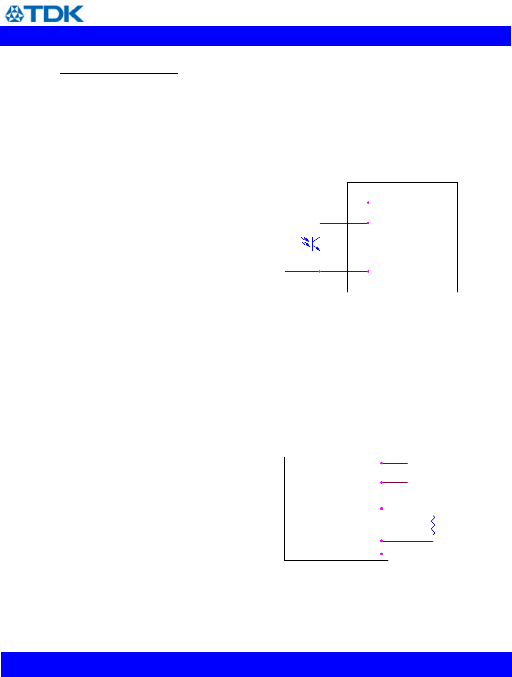
Remote On/Off: - The power modules have
an internal remote on/off circuit. The user
must supply an open-collector or compatible
switch between the Vin(-) pin and the on/off
pin. The maximum voltage generated by the
power module at the on/off terminal is 15V.
The maximum allowable leakage current of
the switch is 50uA. The switch must be
capable of maintaining a low signal Von/off <
1.2V while sinking 1mA.
It is recommended that the power module be
kept off for at least 100mS each time it is
turned off.
The standard on/off logic is positive logic. The
power module will turn on if terminal 2 is left
open and will be off if terminal 2 is connected
to terminal 4. An optional negative logic is
available. The power module will turn on if
terminal 2 is connected to terminal 4, and it
will be off if terminal 2 is left open.
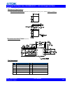
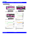
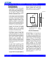
On/ Off
Vin (+)
Vin(-)
An On/Off Control Circuit
Output Voltage Adjustment: The output
voltage of the power module may be adjusted
by using an external resistor connected
between the Vout trim terminal (pin 7) and
either the Sense (+) or Sense (-) terminal. If
the output voltage adjustment feature is not
used, pin 7 should be left open. Care should
be taken to avoid injecting noise into the
power module’s trim pin. A small 0.01uF
capacitor between the power module’s trim
pin and Sense (-) pin may help avoid this.
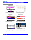
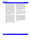
Trim
Vout(-)
Sense(+)
Vout(+)
Sense(-)
Rdown
Circuit to decrease output voltage
With a resistor between the trim and Sense (-)
terminals, the output voltage is adjusted
down. To adjust the output voltage down a