


Advance Data Sheet: Dualeta™ iQA Series – Dual Quarter Brick
©2002-2005 TDK Innoveta Inc.
iQAFullDatasheet080505 2.doc 8/3/2006
℡
(
877
)
498-0099
15/19
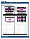
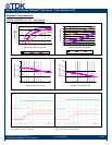
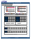
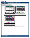
thermal performance figures in the Thermal
Performance section. The curves in the
figures are shown for natural convection
through 3 m/s (600 ft/min). The data for the
natural convection condition has been
collected at 0.3 m/s (60 ft/min) of airflow,
which is the typical airflow generated by
other heat dissipating components in many
of the systems that these types of modules
are used in. In the final system
configurations, the airflow rate for the natural
convection condition can vary due to
temperature gradients from other heat
dissipating components.
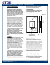
Heatsink Usage: For applications with
demanding environmental requirements,
such as higher ambient temperatures or
higher power dissipation, the thermal
performance of the power module can be
improved by attaching a heatsink or cold
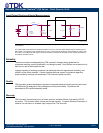
plate. The iQA platform is designed with a
base plate with four M3 X 0.5 through-
threaded mounting fillings for attaching a
heatsink or cold plate. The addition of a
heatsink can reduce the airflow requirement,
ensure consistent operation and extend
reliability of the system. With improved
thermal performance, more power can be
delivered at a given environmental condition.
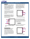
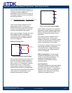
Standard heatsink kits are available from
Innoveta Technologies for vertical module
mounting in two different orientations
(longitudinal – perpendicular to the direction
of the pins and transverse – parallel to the
direction of the pins) as shown in the
heatsink Offering section. The heatsink kit
contains four M3 x 0.5 steel mounting
screws and a precut thermal interface pad
for improved thermal resistance between the
power module and the heatsink. The
screws should be installed using a torque-
limiting driver set between 0.35-0.55 Nm (3-
5 in-lbs).
During heatsink assembly, the base-plate to
heatsink interface must be carefully
managed. A thermal pad may be required to
reduce mechanical-assembly-related
stresses and improve the thermal
connection. Please contact Innoveta
Engineering for recommendations on this
subject.
The system designer must use an accurate
estimate or actual measure of the internal
airflow rate and temperature when doing the
heatsink thermal analysis. For each
application, a review of the heatsink fin
orientation should be completed to verify
proper fin alignment with airflow direction to
maximize the heatsink effectiveness. For
Innoveta standard heatsinks, contact
Innoveta Technologies for latest
performance data.
Operating Information
Over-Current Protection
The power modules have current limit
protection to protect the module during
output overload and short circuit conditions.
During overload conditions, the power
modules may protect themselves by
entering a hiccup current limit mode. The
modules will operate normally once the
output current returns to the specified
operating range. There is a typical delay of
100mS from the time an overload condition
appears at the module output until the
hiccup mode will occur.
Output Over-Voltage Protection
The power modules have a control circuit,
independent of the primary control loop that
reduces the risk of over voltage appearing at
the output of the power module during a
fault condition. If there is a fault in the
primary regulation loop, the over voltage
protection circuitry will cause the power
module to enter a hiccup over-voltage mode
once it detects that the output voltage has
reached the level indicated in the Electrical
Data section for the power module of
interest. When the condition causing the
over-voltage is corrected, the module will
operate normally.
Thermal Protection
When the power module exceeds the
maximum operating temperature, the
module may turn-off to safeguard the power
unit against thermal damage. The module
will auto restart as the unit is cooled below
the over temperature threshold.