


Advance Data Sheet: Dualeta™ iQA Series – Dual Quarter Brick
©2002-2005 TDK Innoveta Inc.
iQAFullDatasheet080505 2.doc 8/3/2006
℡
(
877
)
498-0099
17/19
With a resistor between the trim and Vo (+)
terminals, the output voltage is adjusted up.
To adjust the output voltage up a
percentage of Vout (%Vo) from Vo,nom the
trim resistor should be chosen according to
the following equation:
The maximum power available from the
power module is fixed. As the output
voltage is trimmed up, the maximum output
current must be decreased to maintain the
maximum rated power of the module.
As the output voltage is trimmed, the output
over-voltage set point is not adjusted.
Trimming the output voltage too high may
cause the output over voltage protection
circuit to be triggered.
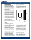
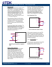
Optional Tracking Trim
Vo2(+)
Rdown
Rdown
(Vo2,nom<2V)
Trim
RTN
(Vo2,nom>=2V)
Vo1(+)
Circuit to decrease output voltage
With a resistor between the trim and Vo2(+)
terminals, the output voltage is adjusted
down. For models where the nominal set
point of Vo2 is < 2V, the resistor is instead
tied from trim to Vo1(+). Refer to the
resistor selection tables in the Electrical
Characteristics section for trim adjustment.
The current limit set point does not increase
as the module is trimmed down, so the
available output power is reduced.
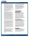
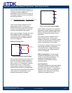
Trim
Vo2(+)
Vo1(+)
RTN
Rup
Circuit to increase output voltage
With a resistor between the Trim and RTN
terminals, the output voltage is adjusted up.
Refer to the resistor selection tables in the
Electrical Characteristics section for trim
adjustment.
The maximum power available from the
power module is fixed. As the output
voltage is trimmed up, the maximum output
current must be decreased to maintain the
maximum rated power of the module.
As the output voltage is trimmed, the output
over-voltage set point is not adjusted.
Trimming the output voltage too high may
cause the output over voltage protection
circuit to be triggered.
EMC Considerations: Innoveta power
modules are designed for use in a wide
variety of systems and applications. For
assistance with designing for EMC
compliance, please contact Innoveta
technical support.
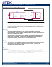
Input Impedance:
The source impedance of the power feeding
the DC/DC converter module will interact
with the DC/DC converter. To minimize the
interaction, a 10-100uF input electrolytic
capacitor should be present if the source
inductance is greater than 4uH.
Rup
3.01Vonom 100 %Vo+()⋅
1.225 %Vo()⋅
301 4.01 %Vo()⋅+
%Vo
−
1000⋅=