Telect, Inc. • USA +1.509.926.6000 • Mexico +52.33.3836.3700
Poland +48.713.239.100 • UK +44.1489.889500 • www.telect.com
Copyright © 2006 Telect, Inc., All Rights Reserved • 130358-2 A0
Page 2
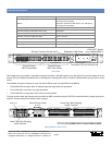
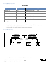
GMT output fuses are available in capacities ranging from 0.18A to 10A. GMT splash covers are optional for maximum safety when fus-
es blow. [Visit our website (www.telect.com) or see Page 9 for ordering GMT fuses.] The panel is delivered with “dummy” fuses in all po-
sitions.
The standard front panel includes a tri-color fuse alarm LED for each circuit (ALARM A & ALARM B):
• The ALARM LEDs are green when all installed input and output fuses are operational.
• The ALARM LED is red when any output fuse blows.
• The ALARM LED is orange when either of the input fuses blows.
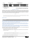
The back contains input and output terminal connections (NEG connections at top; POS RTN connections below), chassis ground con-
nections, and wire-wrap pins for external alarm hookups.
Electrical Specifications
Operating voltages, nominal -24 Vdc to -48 Vdc
Current capacity06004-01
06004-11
20A per bus (40A total for both buses), max. with 20A ce-
ramic input fuse (Type ABC)
15A per bus (30A total for both buses), max, with 20A ce-
ramic input fuse (Type ABC)
Fuse capacity 20 (ea side)
Maximum PDU input interruption device rating 25A per bus
Maximum output interruption device rating 10A GMT fuse
Maximum continuous output load rating 7A for a 10A fuse
Alarm contact relay 2A @ 30 Vdc
Panel heat dissipation per 20A bus 3.9W (13.3 Btu/hr) @ 0% load
Percentage of full load heat dissipation at nominal voltage less than 1% of total load wattage
POWER A
1
5
10
15
20
POWER B
1
5
10
15
20
A
B
FAIL SAFE
A
B
ALARM
20A Input Fuses for Circuits A & B
Fuse Alarm LEDs for Circuits A & B
Designation Card Holder
Circuit A Output
"FAIL SAFE" Applies
only to Model 06004-11
GMT Fuse Holders
Circuit B Output
GMT Fuse Holders
Front View
-A
-B
+A
+B
FAIL
RELAY
NO
C
NC
A
B
NO
C
NC
A
B
-24V
TO
-48V
RTN
CAUTION: DO NOT REVERSE POLARITY
Alarm Pins for Circuits
A & B
Screw-Tight, Wire-Clamping
Input Terminals
Screw-Tight, Wire-Clamping
Output Terminals
* Plastic caps cover screw-tight terminals used by the manufacturer for installing
interior wiring. DO NOT REMOVE CAPS or LOOSEN CLAMPING SCREWS.
Plastic Caps*
Model 06004-01 (Rear View)


