


Telect, Inc. • USA +1.509.926.6000 • Mexico +52.33.3836.3700
Poland +48.713.239.100 • UK +44.1489.889500 • www.telect.com
Copyright © 2006 Telect, Inc., All Rights Reserved • 130358-2 A0
Page 4
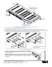
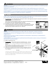
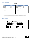
3. Select the proper pair of brackets and discard the other two.
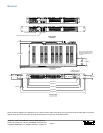
4. Mount brackets to sides of panel, as shown in the following examples. Tighten screws to about 29 in.-lb (~3.3 N•m).
Panel can be mounted so that panel’s face is flush or extended in 0.5-in. (12.7 mm) increments from rack. (The clover-leaf pat-
tern on the face of the bracket points downward on the right side of the panel and upward on the left.)
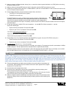
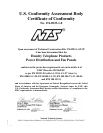
5. Locate an unused rack position and mount panel using four, 12-24 thread-cut-
ting screws and lockwashers provided, as shown on the right. Tighten screws
to 35 in.-lb (4.29 N•m).
6. Before connecting any conductor, use a multimeter to measure the resistance
between the input terminal of each side (+A and -A for Side A; +B and -B for
Side B) at the rear corner of the panel. Expect 500Ω or more for both Side A
and Side B.
Right Bracket
for 19-in. Rack
Left Bracket
for 23-in. Rack
Right Bracket
for 23-in. Rack
Left Bracket
for 19-in. Rack
Remove Screws (4) on Each
Side of Panel to Remove
Brackets from Stowed Position
Panel With Mounting Brackets in Stowed Position for Shipping
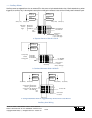
Bracket for a
19-in. Rack
Bracket for a
23-in. Rack
(Flush Mount)
(Flush Mount)
Bracket for a
19-in. Rack
(Extended 2 in.)
Clover-Leaf Pattern Points Downward
on Right Side of Panel.
Bracket Installation (Examples)