


Telect, Inc. • USA +1.509.926.6000 • Mexico +52.33.3836.3700
Poland +48.713.239.100 • UK +44.1489.889500 • www.telect.com
Copyright © 2006 Telect, Inc., All Rights Reserved • 130358-2 A0
Page 5
WARNING
!
WARNING! Failure to properly ground this equipment can create hazardous conditions to installation person-
nel and to the equipment.
WARNUNG! Bei unsachgemäßer Erdung besteht Gefahr für das Installationspersonal und das Gerät!
¡AVISO! La conexión incorrecta a tierra puede ser peligrosa tanto para los instaladores como para el equipo.
AVERTISSEMENT! Si vous ne reliez pas correctement cet équipement à la terre, son utilisation présente des
dangers pour la personne qui l'installe ainsi que pour l'équipement.
ALERT
!
ALERT! Only use components and crimping tools approved by agencies or certifying bodies recognized in
your country or region such as Underwriter’s Laboratories (UL), TUV, etc.
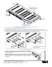
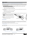
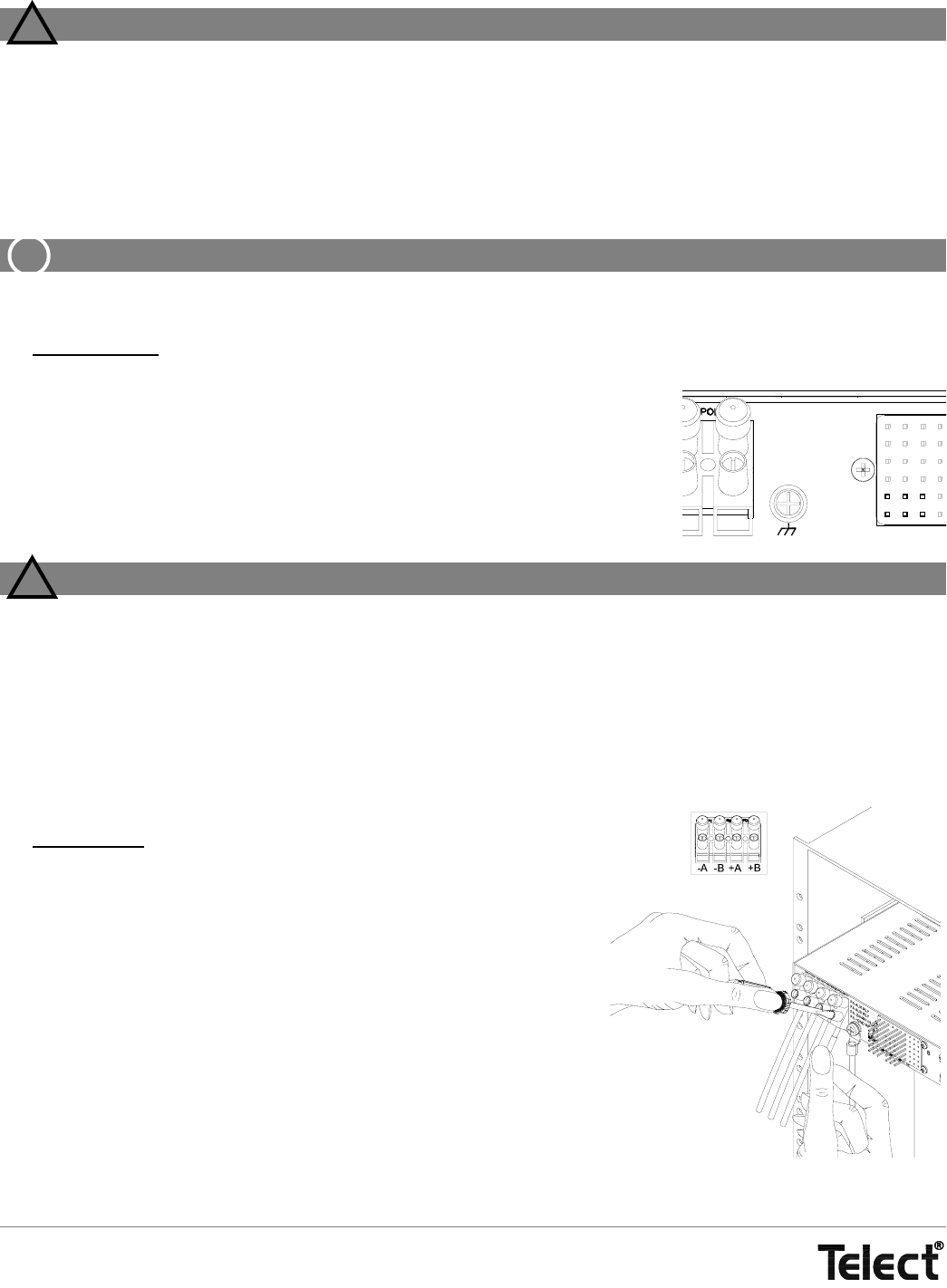
7. For ground wiring, use a listed (approved) crimping tool to attach a listed (approved), single-hole compression lug suitable for a
#10 (~5 mm) stud onto a suitable ground wire.
Ground wire should be same gauge as input wiring. Input wire size depends solely on in-
put interruption device at the primary distribution unit (PDU).
8. If necessary, use a coarse, nonmetallic cleaning pad to clean lug and stud.
9. Telect recommends that you lightly coat anti-oxidant on lug, grounding screw, and sur-
rounding contacting surface. Connect lug to rear panel using #10 ground provided,
shown on the right. Tighten screws to 20 in.-lb (~2.26 N•m).
WARNING
!
WARNING! Before connecting input power cables, make sure input power to panel is turned off.
WARNUNG! Vor Anschluss der Eingangsstromkabel ist sicherzustellen, dass der Eingangsstrom
ausgeschaltet ist.
¡AVISO! Antes de conectar los cables de entrada de la alimentación, compruebe que la alimentación de
entrada al panel está cortada.
AVERTISSEMENT! Avant de connecter les câbles d'entrée d'alimentation, assurez-vous que l'alimentation
électrique est coupée au panneau.
10. Make sure input power is off.
11. For input wiring
— wiring used as inputs to this distribution panel — strip ap-
proximately
3
/8 in. (~10 mm) of insulation from the end of suitable input con-
ductors.
Input conductor (14 to 6 AWG) must match or exceed the rating of the fuse or
breaker at the PDU. (Stranded wires should be tinned.)
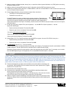
12. Lightly coat anti-oxidant on bare conductors insert the conductors at the bot-
tom of the screw-tight terminals, as shown on the right. Tighten screws to 16
in.-lb (1.80 N•m).
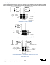
Important
-24 Vdc and -48 Vdc always goes to -A and -B and +24 Vdc always goes to +A
and +B, depending on CO or base-station power. RTN always goes to the oth-
er terminal. For Model 06004-11 with fail-safe circuitry, make sure that RTN is
common to both Side A and B.
FAIL
RELAY
NO
C
NC
A