


Page 11
Calibration and Adjustments
SECTION 3
This section contains instructions to change the configuration of the power supply from the way
it was set up at the factory.
3.1 Range Change:
Since the display uses a 3-1/2 digit LCD, the highest number that can be displayed is 1999. If
the display is to read directly in the flow units being used, it must be adjusted whenever the highest
digit of the maximum flow rate changes, such as, a 20 SLPM flow instrument being changed to 5
SLPM. If a 10 SLPM unit is exchanged for a 10 SCCM unit, the display will not need to be
changed at all. If a 5 SLPM unit is changed to a 500 SCCM unit, then only the decimal point needs
to be changed, per Section 3.1.2.
3.1.1 Displa3.1.1 Displa
3.1.1 Displa3.1.1 Displa
3.1.1 Displa
y y
y y
y
AdjustmentAdjustment
AdjustmentAdjustment
Adjustment
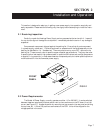
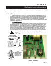
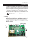
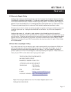
To change the display, remove the two screws on the top of the back panel. Slide the aluminum
perforated top cover out. Turn the CHANNEL SELECTOR switch to the desired channel. Verify
that the conversion factor has been set to the correct value, by depressing the CORRECTION
FACTOR switch. The correction factor should be 1.000 if the factor has not been changed by the
customer since the factory setup. If the value has been changed by the customer, determine the
correct value for the gas flowing through the flowmeter per Section 3.2. Compare the observed
value to the calculated value. Generate the maximum flow signal (5.000 volts) from the flowmeter,
Switches are shown
set for one place
to the right of the
decimal point for
Channel 3.
DISPLAY-ADJUST
POTENTIOMENTERS
FRONT of PANEL
CHANNELSCHANNELS
CHANNELSCHANNELS
CHANNELS
FIG 3.1FIG 3.1
FIG 3.1FIG 3.1
FIG 3.1
Not operator serviceable, observe precautions when handling, do not pull cover further
back more than necessary, some components toward the rear of the PC Board may be
High High
High High
High
VV
VV
V
oltage,oltage,
oltage,oltage,
oltage,
leave servicing to qualified personnel
..
..
.
4 3 2 1