Page 8
2.3 Output Voltage:
The output of the flow instrument is a 0-5.00 VDC signal proportional to the flow rate. The
output is sent to the display and is available at terminals at the rear of the Model 40 Power Supply.
It is recommended that the load resistance be no less than 2K Ohms.
2.4 Electrical Connection:
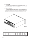
Ensure that the power switch is turned off. Plug the AC line cord into an appropriately rated
receptacle. Then plug the 15 pin D connector cable, purchased separately from Hastings Instru-
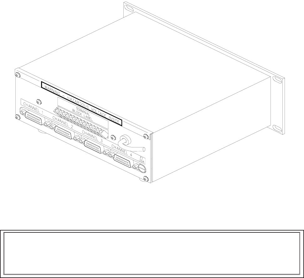
ments, into the top of the flow instrument and into the back of the power supply. When looking at
the back panel of the power supply the different channels are numbered from left to right (see
Figure 2.2).
Figure 2.3 shows a close-up of the terminal block label.
FIG 2.3
15
VDC
COMMON
-15 VDC
COMMON
NC
COMMON
NC
COMMON
CHANNEL 1
FLOW OUT
CHANNEL 2
FLOW OUT
CHANNEL 3
FLOW OUT
CHANNEL 4
FLOW OUT
FLOW
COMMON
CASE GND
FIG 2.2


