


Page 15
Troubleshooting
SECTION 4
This section contains a troubleshooting guide to help locate and repair failed components.
This troubleshooting guide is designed as a general reference only, and will not cover every possible
component failure. It is possible for problems with theflow instruments to appear as a failed power
supply and vice versa. Therefore, if possible, try to verify the proper operation of the flow instru-
ments on a different power supply. The components and test points mentioned in this section can
be located by referring to the component layout drawing in Section 6.0.
NOTE: SOME OF THE TROUBLESHOOTING PROCEDURES WILL INVOLVE RE-
PLACING FAILED COMPONENTS ON THE PRINTED CIRCUIT BOARD. DO NOT
PERFORM THESE STEPS IF THE POWER SUPPLY IS STILL UNDER WARRANTY, SINCE
PRINTED CIRCUIT BOARD MODIFICATIONS WILL VOID THE WARRANTY.
TP5TP5
TP5TP5
TP5
TP3TP3
TP3TP3
TP3
TP2TP2
TP2TP2
TP2
FRONT of PANEL
TP6TP6
TP6TP6
TP6
TP1TP1
TP1TP1
TP1
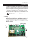
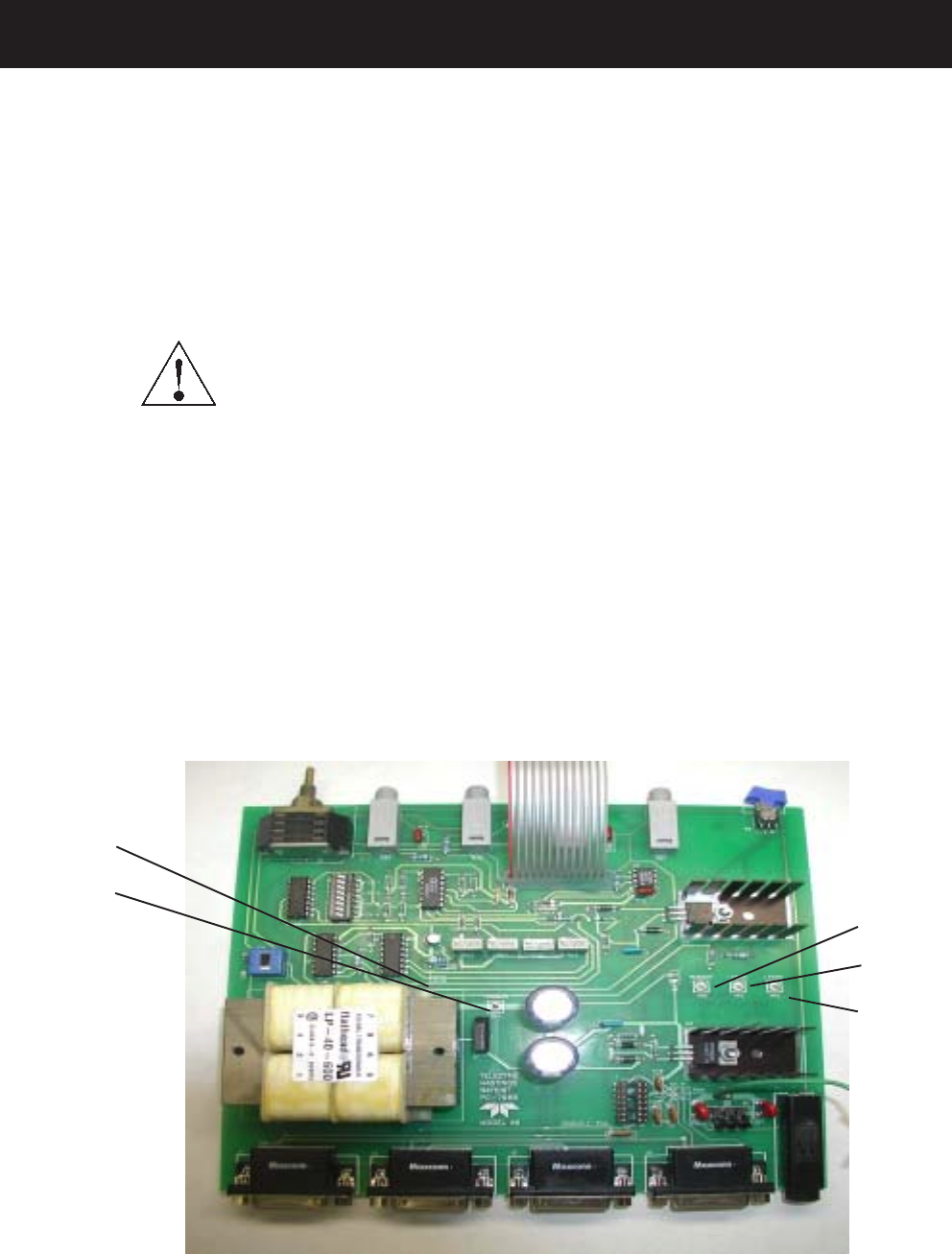
FIG 4.1
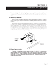
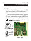
4.1 Test Points:
Refer to Figure 4.1. Test point 1 (TP-1) is common. All of the voltages specified in this section
are referenced to this point unless stated otherwise. These voltages should be checked under load
condition. Test point 2 (TP-2) is the output of the positive regulator and should read between
+14.25 and+15.75 VDC. Test point 3 (TP-3) is the output of the negative regulator and should
read between -14.25 and -15.75 VDC. Test point 5 (TP-5) is the voltage applied to the front panel
display. Since the display is a miniature digital voltmeter, the voltage on TP-5 should be the same
as the number on the display.
Some components on the PC Board are at
High High
High High
High
VV
VV
V
oltage,oltage,
oltage,oltage,
oltage,
only qualified personnel
should perform this test
..
..
.