Page 10
2.5.5 Fuse2.5.5 Fuse
2.5.5 Fuse2.5.5 Fuse
2.5.5 Fuse
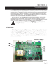
The fuseholder is mounted on the lower right-hand corner of the back panel. To remove the
fuse, insert a screwdriver into the slot and turn counterclockwise 1/4 turn. Replace the fuse with a
250 volt 1/4 amp Slo-Blo<190> fuse, 1/4" x 1-1/4". Insert fuse into fuseholder. Place into fuse base
and turn clockwise 1/4 turn. Attempting to turn past the stop may damage the fuseholder.
2.5.6 Rear 2.5.6 Rear
2.5.6 Rear 2.5.6 Rear
2.5.6 Rear
TT
TT
T
erer
erer
er
minal Boardminal Board
minal Boardminal Board
minal Board
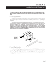
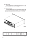
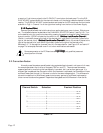
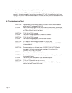
There is a 14-position terminal board on the rear panel . See Fig. 2.4. The pins are numbered
from left to right. Pin 1 is the 15 VDC regulated output of the power supply. Pin 3 is the -15 VDC
regulated output of the power supply. These terminals can supply up to 150 mA each for use in
external display boards, etc. Pins 2, 4, 6, 8 and 13 are common for both the positive and negative
supplies. All five of these terminals are tied together internally. Pins 7 - 10 are the 0 - 5 VDC flow
output signals from the flowmeters on channels 1 - 4 respectively. All four of the terminals can be
monitored simultaneously. These signals are referenced to pin 13 (flow common) and to the power
supply common terminals.


