Page 7
Installation and Operation
SECTION 2
This section is designed to assist you in getting a new power supply into operation as quickly and
easily as possible. Please read the following very thoroughly before attempting to install the instru-
ment.
2.1 Receiving Inspection:
Carefully
unpack the Hastings Power Supply and any accessories that arrive with it. Inspect it
for any obvious signs of damage due to shipment. Immediately advise the carrier if any damage is
suspected.
Compare each component shipped against the packing list. Ensure that all parts are present
(i.e. power supply, cables, etc.). Optional equipment or accessories will be listed separately on the
packing list (see Section 1.4 - Accessories). There may also be one or more OPT- options on the
packing list. These normally refer to special ranges or special gas calibrations. They may also refer
to special helium leak tests or high pressure tests, or special modifications such as high temperature
or special O-ring materials. In most cases these are not separate parts, but rather special options or
modifications built into the flowmeter power supply.
2.2 Power Requirements:
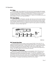
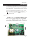
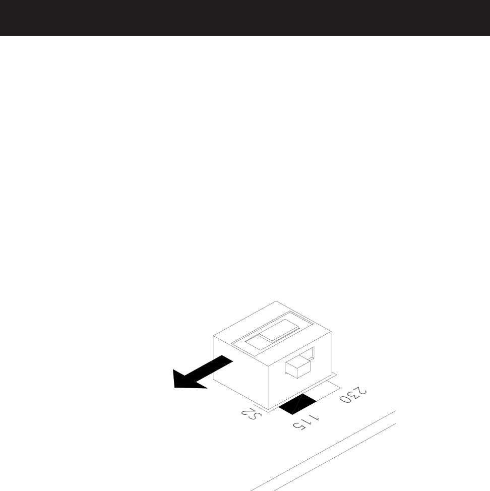
The Model 40 Power Supply normally operates on either 115 or 230 VAC. It can be switched
between these two supplies by the black switch next to the transformer on the PC board, front left
corner (see Figure 2.1). Access the switch by removing two top screws in the rear panel and sliding
the top cover aft. 115 and 230 positions are marked on the PCB. Units will be shippedfor the
voltage specified in the order.
FIG 2.1
FRONT
PANEL


