


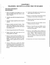
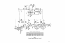

CIRCUIT DESCRIPTION
TRANSMIT BOARD
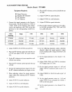
ALIGNMENT PROCEDURE
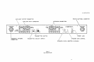
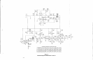
U50IC is an amplifier whose gain is controlled by
the level
of
audio entering the rectifier at pin 16.
As the level here increases, the gain is decreased
and this results in a 2:1 compression characteristic.
Pre-emphasis is added by U501B. R504, R505,
and C508 set this at 115uS. C531 rolls the response
off above
10KHz
to
further attenuate the 20 KHz
call signal (see Audio Board Circuit Description).
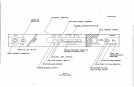
Q501 is a Colpitts oscillator with the collector
tuned
to
the third harmonic. T501, VVC501 and
VVC502 are added in
selies with the crystal
to
allow frequency modulation
of
the oscillator. The
oscillator is operated
10KHz
below the series
resonant point
of
the crystal. This improves
linearity at the expense
of
some stability. Q502 is a
trip1er and Q503 is a straight through amplifier.
The catTier frequency is thus nine times the crystal.
C529, C530 and L503 function as a low pass filter
and matching network.
3-2
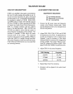
EQUIPMENT
REQUIRED:
o RF POWER METER
o FREQUENCY COUNTER
o DC VOLTMETER
1.
Connect the RF power meter and frequency
counter
to
the Transmit Antenna jack. Make
sure the Transmit switch
on
the
reat·
panel is set
the the Cont position.
2.
Adjust T502, T503, T504, VC501, and VC502
for maximum power. Note:
If
adjustments are
severly out
of
alignment and no output can
be
obtained, it may be necessmy
to
first adjust
T502 and T503 for maximum DC voltage at the
emitter
of
Q502. Then adjust T504 for maxi-
mum
DC
voltage at the emitter
of
Q503. Now
adjust VC501and VC502 for maximum power.
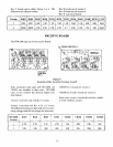
3. Adjust T501 for the
COlTeCt
frequency:
Y501 Marking Frequency
154T570
154.570
177T800
177.800
183T730
183.730
4.
Repeat Steps 2 and 3 as necessmy.
5. Deviation
will
be adjusted
in
the audio board
alignment.