


Ext
Intercom Switch, Level Control,
and
In-
dicator: This switch enables the wired intercom
interface when "IN", and disables it when "OUT".
For
RTS
intercoms, the "IN" position is channel A
and the "OUT" position ischannel B. Ascrewdriver
adjustable control is provided to control the input
level
of
the wired intercom.
Auxiliary Audio
Enable
Switch, Level Control,
and
Indicator:
Theswitch enables and disables the
Auxiliary intelface when "IN" and "OUT", respec-
tively. The function
of
the level control here is the
same as that described for the intercom.
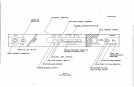
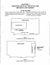
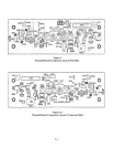
REAR
PANEL (Refer to Figure 3)
(j
Transmit
Antenna
Connector: Connect5/8-wave
antenna (supplied)
to
this connector. Antennacolor
should match connector dot
on
BTR-200.
Receive
Antenna
Connector: Connect 5/S-wave
antenna (supplied)
to
this connector. Antenna color
should match connector dot
on
BTR-200.
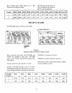
Transmit
Switch: Slide switch that allows the
operator
to
select one
of
three transmit modes.
In
the "OFF" position, the transmitter is always off.
This mode may be used
if
the base is functioning
solely
as
a monitor. In the "CONT" position, the
transmitter is always on. This continuous mode is
recommended over the "REMOTE" mode. In the
"REMOTE" position, the transmitter is enabled
only when one or more portables are active.
Headset Microphone Select Switch: This switch
allows the user to select either
an
Electret
or
Dynamic microphone. This switch
i~
factory preset
to
DYN Position.
NOTE: All Telex headsets that are used with this
intercom are dynamic type microphones.
Intercom
Connectors: Connections to interface
the BTR-200 with a wired intercom system.
Auxiliary
Output/Input
Connectors:
Can
be
used for 2-way (four wire) input and output to the
BTR-200 or as a simplex input or output. Typical
uses are 4 wire low level intercoms, tape recorders,
public address inputs or outputs, or when operating
two BTR-200 units simultaneously.
Power
Jack:
For external AC wall supply adaptor
(supplied) or any filtered 12 to 14
VDC/300 rnA
source, or 13.0
VAC
RMS/300 rnA source.
Speaker
Jack:
Allows the user to connect an ex-
ternal speaker
(8
ohms minimum)
to
the unit.
Speaker
Gain
Control: Screwdriver adjustable.
Adjust the gain control clockwise to increase
speaker gain
or
counterclockwise
to
decrease
speaker gain.
NOTE: Leave setting counterclockwise
if
no
speaker is attached.
1-511-6
Blank