


4. Connect the signal generator
to
the Receive
Antenna jack. Set the deviation
to
± 3 KHz at
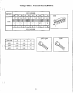
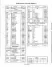
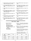
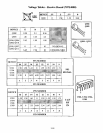
I KHz. Referto thechart and selectthe channel
3 frequency.
5. ConnecttheAF voltmeter, distortion meter, and
SINAD meter
to
U421 pin
1.
6.
Adjust VR421
to
maximum counterclockwise.
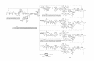
7.
Adjust
VC301,
VC302,
VC303,
VC304,
VC305 and VC306 for best SINAD.
8.
Increase signal generator output
to
I m
V.
9 Adjust L422 for maximum audio.
lOA.
Version I: Adjust L421 and L422for minimum
distortion.
lOB. Version
2:
Adjusut L421, L422 and L423 for
minimum distortion.
11.
Adjust VR420 for 140 mV
of
audio.
12.
Set the signal generator output
to
I
!-tV.
13.
Adjust VR421 fully clockwise, then turn it
counterclockwise until the number 3 LED
on
the front paneljust comes on.
14.
Set the signal generator to the channel I fre-
quency and increase the output
to
1 m
V.
15.
Move the audio hook up to U321 pin I.
16.
Adjust L322 for maximum audio.
17
A.
Version I: Adjust L321 and L322 for minimum
distortion.
17B. Version
2:
Adjust L321, L322, and L323 for
minimum distortion.
18.
Adjust VR320 for 140 mV
of
audio.
19.
Set the signal generator output
to
I
!-tv.
20. Adjust VR321 fully clockwise, then turn it
counterclockwise until the number I LED on
the front panel justcomes on.
21. Set the signal generator
to
the channel 2 fre-
quency and increase the output
to
I m
V.
22. Move the audio hook up
to
U371 pin I.
23. Adjust L372 for maximum audio.
24A. Version I: AdjustL371 and L372 for minimum
distortion.
24B. Version
2:
Adjust L371, L372, and L373 for
minimum distortion.
25. Adjust VR370 for 140 mV
of
audio.
26. Set the signal generator output
to
1
!-tv.
27. Adjust VR371 fully clockwise, then turn it
counterclockwise until the number 2 LED
on
the front panel just comes on.
28. Set the signal generator
to
the channel 4 fre-
quency and increase the output
to
I m
V.
29. Move the audio hook
up
to
U471 pin
1.
30. Adjust L472 for maximum audio.
31
A.
Version I: Adjust L471 and L472 for minimum
distortion.
31
B.
Version
2:
Adjust L471, L472, and L473 for
minimum distortion.
32. Adjust VR470 for
140
mV
of
audio.
33. Set the signal generator output
to
I
!-tv.
34. Adjust VR471 fully clockwise, then turn it
counterclockwise until the number 4 LED on
the front paneljust comes on.
3-12