


14
Cables
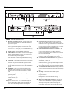
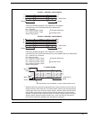
The numbers below correspond to the cable numbers in the connection drawings on the following pages.
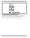
• 1-channel intercom cable. Sold Separately. Use Telex ME cables, below. Or, build per Figure 7 on page 19.
ME-25: 25’ (7.6 m) cable with Male and Female 3-pin XLR connectors.
ME-50: 50’ (15.2 m) cable with Male and Female 3-pin XLR connectors.
ME-100: 100’ (30.4 m) cable with Male and Female 3-pin XLR connectors.
NOTE: When connecting from the MS-2002 to a TW-7W, keep cables as short as possible. Also, heavier gage wire
is recommended.
• 2-channel intercom cable. Sold separately. Use Telex ME/2 cables, below. Or build per Figure 7.
ME-25: 25’ (7.6 m) cable with Male and Female 6-pin XLR connectors.
ME-50: 50’ (15.2 m) cable with Male and Female 6-pin XLR connectors.
ME-100: 100’ (30.4 m) cable with Male and Female 6-pin XLR connectors.
• Y adapter cable. Sold Separately. Use Telex CA-23-16. Or, build per Figure 7 on page 19.
• 3 ft. (0.91 m) speaker cable with RCA plugs. One (1) supplied with each SPS-2001, and SPK-2000.
• 18” (457 mm) EXP IN/OUT cable, stereo miniplug to stereo miniplug. One (1) supplied with each EMS-4001.
• 18” (457 mm) CHANNEL OUTPUT cable, 15-pin Male D-Sub to 15-pin Male D-Sub. One (1) supplied with
each EMS-4001. (Optional component.)
REFERENCE: See EMS-4001 User Manual (P/N 93507713-000) which can be found at http://www.telexaudiocom.com/
manuals.php for connection information.)
• Shielded patch cable, 9-pin Male D-Sub to 9-pin Female D-Sub. Customer local purchase. Available at most
electronic stores.
NOTE: All pins must be connected straight through: do not use an RS-232 computer cable.
• Shielded patch cable, stereo miniplug to stereo miniplug. Customer local purchase. Available at most electronic
stores.
• Shielded audio cable. Must have male 3-pin XLR connector at one (1) end for connection to the XP-USPG or
XP-4PGM program inputs. Pin-out for program inputs is as follows:
Pin 1: common
Pin 2: + program input
Pin 3: - program input
• Shielded audio cable. Must have male 3-pin XLR connector at one(1) end for connection to the XP-USPG PA
output. Pin-out for PA output is as follows:
Pin 1: common
Pin 2: + program input
Pin 3: - program input
• 18” (457 mm) CHANNEL OUTPUT cable, 15-pin Male D-Sub to 15-pin Female D-Sub. One (1) supplied with
each XP-ES4000A. (Optional component.)
REFERENCE: See EMS-4001 User Manual (P/N 93507713000) which can be found at http://www.telexaudiocom.com/
manuals.php for connection information