


15
Specifications
General
Power Requirements:
AC Input: 100-240VAC, 50/60Hz
Channel Power: 24VDC nominal (12 to 30 VDC), 65 to 150mA
MS2002 is capable of supplying 2 amps overall (1 Amp per
channel)
Dimensions:
1.75” (44.5mm) high x 19” (483mm) wide x 10.31” (261.9mm)
deep
Weight:
Approximately 4.5lb. (2kg)
Environmental Requirements:
Storage: -20°C to 80°C (-4°F to 176°F)
0% to 95% humidity, non-condensing
Operating: -15°C to 60°C (5°F to 140°F)
0% to 95% humidity, non-condensing
Dynamic-mic Headset
Microphone:
50 to 200 Ohm, dynamic (balanced or unbalanced)
Headphones:
150 to 600 Ohm, monaural
Connector Type: XLR-4M
Pin 1 - Microphone low
Pin 2 - Microphone high
Pin 3 - Headphone high
Pin 4 - Headphone low
Panel Microphone Input
Microphone Type: Electret condenser
Power:
Phantom (+5VDC)
Nominal Level:
-42dBu
Maximum Level:
-25dBu
Connector Type:
IKP12 (MCP-90 series, stereo plug connector)
Program Input
Input Level:
100mV maximum
Voltage Gain:
25 ±3dB
Output Level (to intercom channel):
1.0V
RMS nominal, 2.3VRMS max.
Input Impedance:
75k Ohm
Common Mode Rejection:
Greater than 50dB
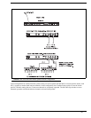
Connector Type: 9-pin female D-Sub (DE9S)
Pin 1 Ground
Pin 2 Program 1 input low
Pin 3 Program 2 input low
Pin 4 NC
Pin 5 NC
Pin 6 Program 1 input high
Pin 7 Program 2 input high
Pin 8 NC
Pin 9 NC
Intercom Channels, Balanced Mode (Both Back Panel and Internal
Switches (BAL/UNBAL) must be set to the same setting)
Output Level:
1V
RMS nominal
Input Impedance:
300 Ohm
Bridging Impedance:
Greater than 10,000 Ohm
Sidetone:
-40dB, 35dB, adjustable range
Call Signaling:
Send: 20kHz ±100 Hz, 0.5V
RMS ±10%
Receive: 20kHz ±800 Hz, 100mV
RMS
Mic-Kill Frequency:
Send: 24kHz ±300Hz, 0.5V
RMS ±10%
Detect: 24kHz ±800Hz, 100mV
RMS
Noise Contribution:
Less than -70dB
Common Mode Rejection Ratio:
Greater than 50dB
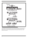
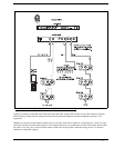
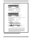
Connector Type: One (1) XLR-3M and XLR-3F pair, wired in parallel, for
each channel (permits “loop-thru” connection). Two (2) XLR-6M (Neutrik)
connectors for 2-channel connection
XLR-3 Balanced Configuration Pinouts
Pin 1 Common
Pin 2 Intercom audio low and +24 VDC input
Pin 3 Intercom audio high and +24 VDC input
XLR-6 Balanced Configuration Pinouts
Pin 1 Audio and DC Common
Pin 2 Local Power (12 to 15 VDC, 65 to 150mA)
Pin 3 Intercom channel 1 audio low and +24VDC phantom power
Pin 4 Intercom channel 1 audio high and +24VDC phantom power
Pin 5 Intercom channel 2 audio low and +24VDC phantom power
Pin 6 Intercom channel 2 audio high and +24VDC phantom power
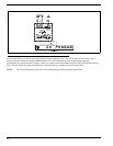
Intercom Channel, Unbalanced Mode (Both Back Panel and Internal
Switches (BAL / UNBAL) have to be set to the same setting).
Output Level:
1V
RMS ±10%
Input Impedance:
150 Ohm
Bridging Impedance:
Greater than 10,000 Ohm
Call Signaling:
Send: 11 ±3VDC
Receive: 4VDC minimum